5 Parameters 01.99
6FC5198-6AA60-0BP1 © Siemens AG 1999 All Rights Reserved
5-10 SINUMERIK 840C, OEM Version for Windows (BA)
S
S
S
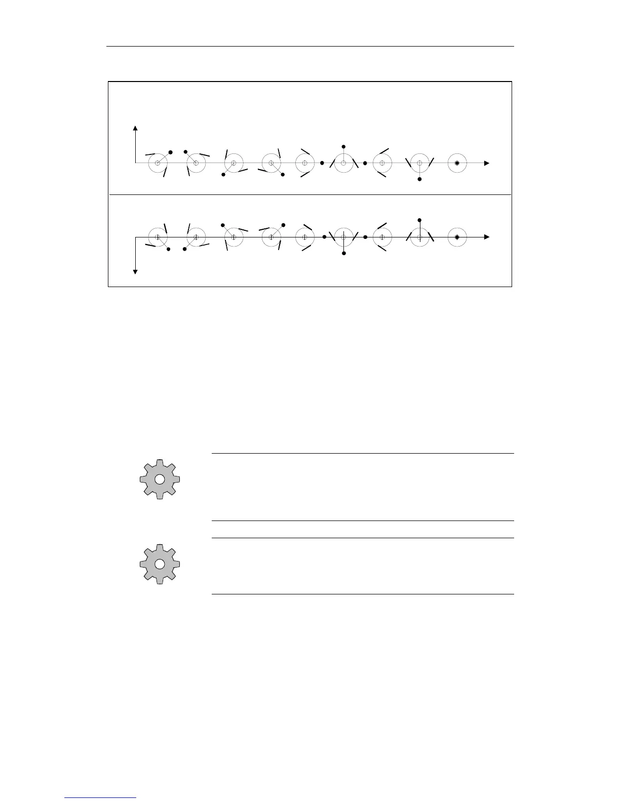
+X
+Z
P1 = 1 P1 = 9P1 = 8P1 = 7P1 = 6P1 = 5P1 = 4P1 = 3P1 = 2
P = S
+X
+Z
P1 = 1 P1 = 9P1 = 8P1 = 7P1 = 6P1 = 5P1 = 4P1 = 3P1 = 2
P = S
Tool point direction when machining
behind
the turning centre
Tool point direction when maching
in front
of the turning centre
P
P
S
P
Fig. 5-6 Tool point direction
L1 geometry, L2 geometry, diameter/radius.
See Fig. 5-5 Tool types.
L1 wear, L2 wear, diameter/radius. For the TO parameters "5" to "7", it is
possible (but not absolutely necessary) to enter the wear data of the tool in the
input screenform.
L1 base, L2 base.
The TO parameters "8" and "9" are provided for special applications. The
"Base dimension" makes a further tool length compensation possible.
Machine manufacturer
It is possible to disable input of the geometry and wear data of the tool by
means of a keyswitch. Please refer to the machine-tool manufacturer’s
documentation!
Machine manufacturer
The maximum standard wear value in parameters P5 to P7 is 9.999 mm.
This limit can be modified by the machine manufacturer.
TO parameters
2 to 4
TO parameters
5 to 7
TO parameters
8 and 9

 Loading...


