Configure hotkeys and PLC keys
4.3 PLC interface
Expanding the user interface
4-14 Commissioning Manual, 11/2006, 6FC5397-0DP10-0BA0
Structure of the interface
The interface between HMI Embedded sl and the PLC uses the following data:
HMI 1: DB19.DBW28: Screen number
DB19.DBB30: Control bits PLC → HMI, PLC byte
DB19.DBB31: Control bits HMI → PLC, HMI byte
HMI 2: DB19.DBW28: Screen number
DB19.DBB80: Control bits PLC → HMI, PLC byte
DB19.DBB81: Control bits HMI → PLC, HMI byte
PLC-Byte Bit0 Display selection
Bit1 Display selection
HMI byte Bit0 Display selection or display deselection accepted
Bit1 Display is being selected or deselected
Bit2 Display is selected
Bit3 Display is deselected
Bit4 Error, display selection not possible
Bit7 Inactive bit
Two bytes are used for the display number to be transferred by the PLC; these are one PLC
byte and one HMI byte for coordinating the display selection.
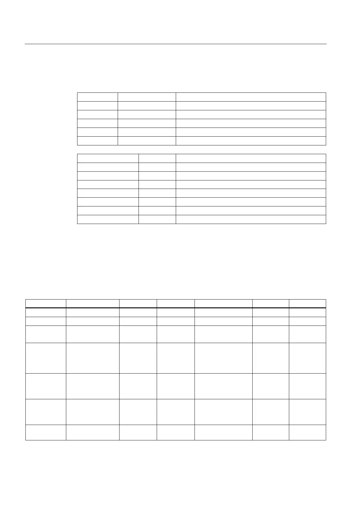
Operating the interface
The interface is operated by the PLC program supplied by the manufacturer, using the
following functions (DB 19 extract, first HMI interface):
PLC → HMI Selection Deselection HMI → PLC Selection Deselection
DBW 28 Screen number (1)
Bit DBB 30 DBB 31
0 Display selection 1 (2)
0 (4)
Select/deselect
accepted
1 (3)
0 (6)
1 (2)
0 (3)
1 Display deselection 1 (1)
0 (4)
Display is being
selected
Display is being
deselected
0 (3)
1 (5)
0 (3)
2 Display is selected 0 (3)
1 (7)
0 (3)
3 Display is deselected 0 (3) 0 (2)
1 (3)
4 Error, display
selection not possible
0 0 (2)