Parameterizing/addressing
9.4 Description of parameters
SIPART PS2 with and without HART
164 Operating Instructions, 10/2013, A5E00074631-11
Description of parameters 13 through 33
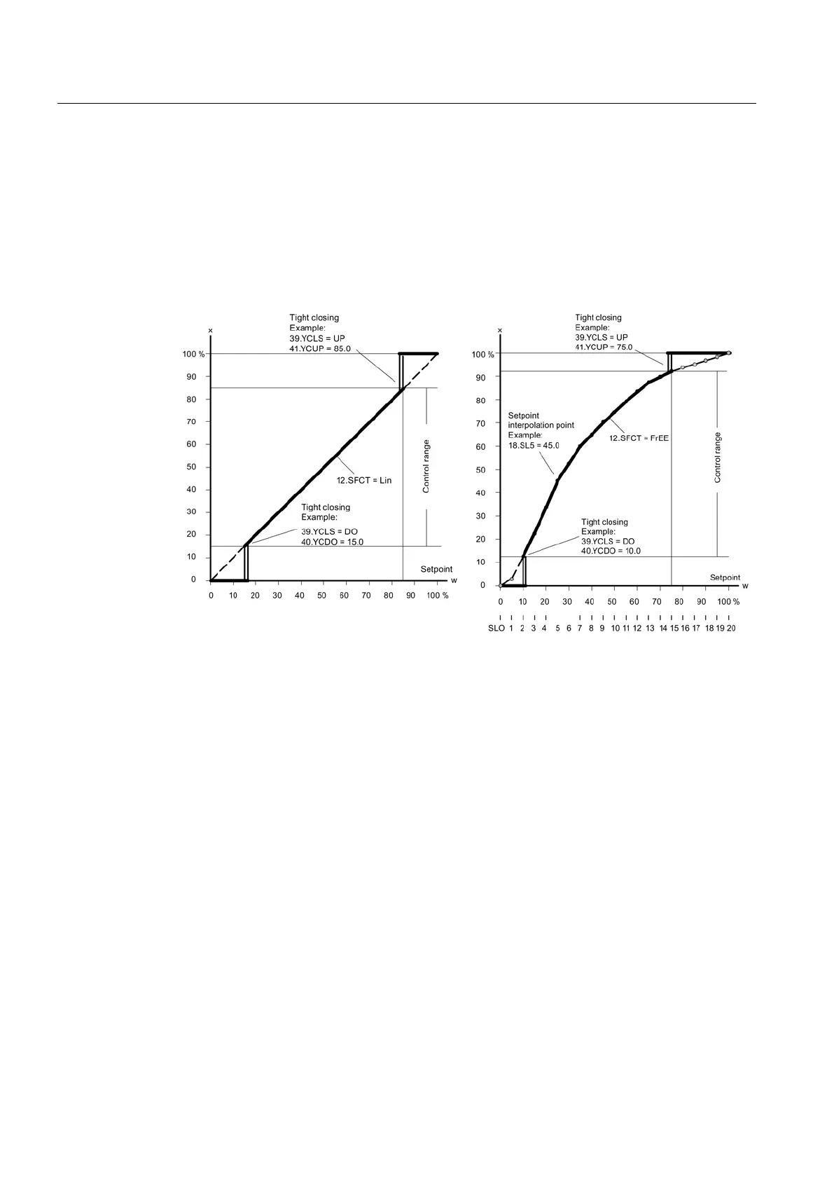
13.SL0 bis 33.SL20 - Setpoint interpolation points
These parameters are used to assign a flow coefficient in units of 5% to each setpoint
interpolation point. The setpoint interpolation points form a polygonal curve with 20 linear
segments, which models the valve characteristic:
Setpoint characteristic curves, standardization of manipulated variables, and tight closing
Input of the setpoint interpolation points is only possible for setting "12.SFCT = FrEE". You
can only enter one monotone rising characteristic curve and two consecutive interpolation
points must differ by at least 0.2%.
The factory setting is "0", "5" ... "95", "100".
Description of parameters 12 (Page 163)
 Loading...


