Installing/mounting
4.7 Installing option modules
SIPART PS2 with and without HART
62 Operating Instructions, 10/2013, A5E00074631-11
Setting the limits of the mechanical limit switch module
Setting the L1 and L2 limits
To set the limits proceed as follows. The serial numbers refer to the image in the chapter
"Mechanical limit switch module (Page 60)".
1. Move the actuator to the first desired mechanical position.
2. Adjust the upper actuating disk
④ manually until the output signal at terminals 41 and 42
changes. Set a high-low or a low-high switchover as follows:
– Rotate the actuating disc beyond the switching point until you reach the next switching
point.
3. Move the actuator to the second desired mechanical position.
4. Adjust the lower actuating disk
⑤ manually until the output signal at terminals 51 and 52
changes. Set a high-low or a low-high switchover as follows:
– Rotate the actuating disc beyond the switching point until you reach the next switching
point.
Note
The actuating discs are relatively difficult to move. This design prevents their
unintentional movement during operation. You can achieve an easier and finer
adjustment by reducing friction temporarily. Move the actuator to and fro while
simultaneously holding the actuating discs.
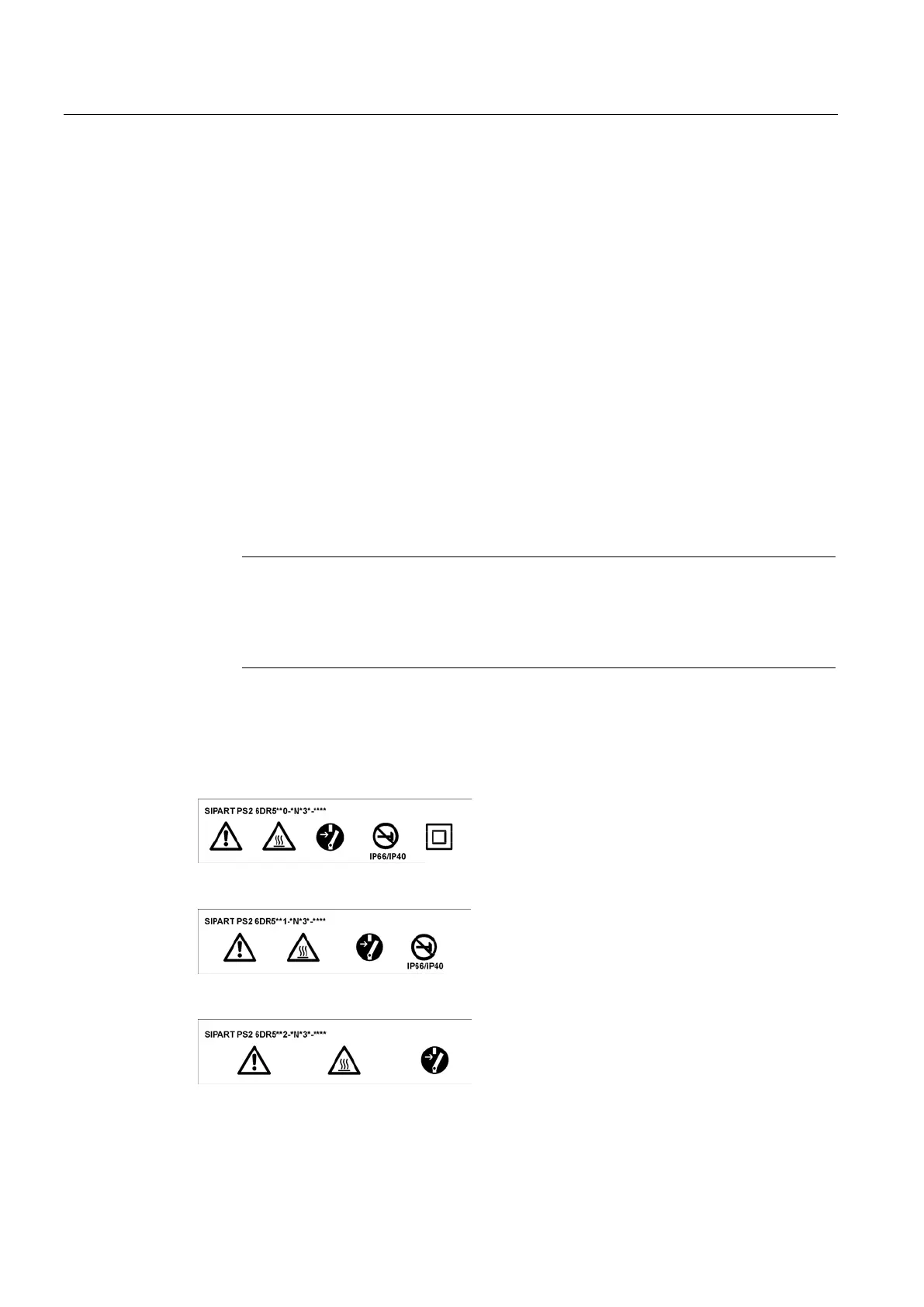
Label set for limit contact module
Fasten the included warning label on the side across from the nameplate. There are different
warning labels depending on the enclosure material, as described below.
Figure 4-15 Warning label for a device with a Macrolon enclosure
Figure 4-16 Warning label for a device with an aluminum enclosure
Figure 4-17 Warning label for a device with a stainless steel enclosure

 Loading...


