Description
3.3 Device components
SIPART PS2 with and without HART
Operating Instructions, 10/2013, A5E00074631-11
25
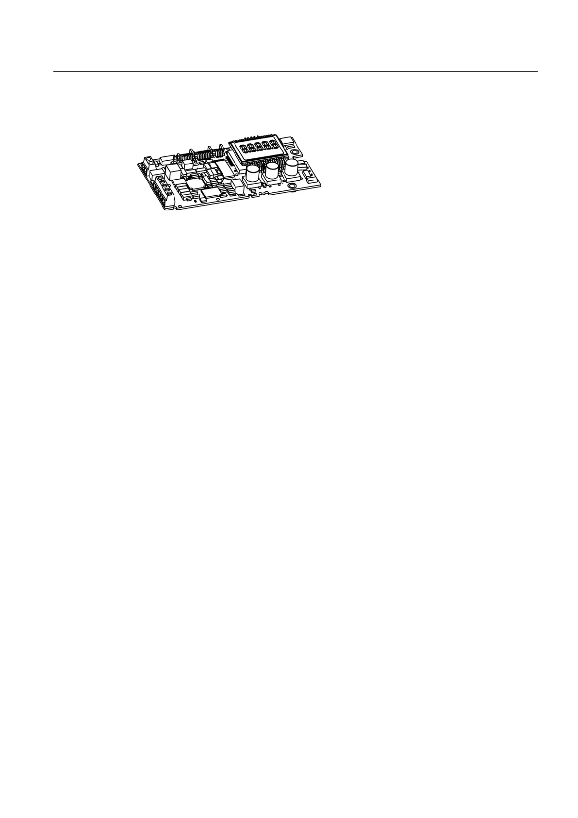
Figure 3-10 Basic electronics
The basic electronics contains:
● CPU
● Memory
● Analog-to-digital converter
● Display
● Buttons
● Terminal strips to connect the option module to the basic electronics
 Loading...


