Installing/mounting
4.7 Installing option modules
SIPART PS2 with and without HART
58 Operating Instructions, 10/2013, A5E00074631-11
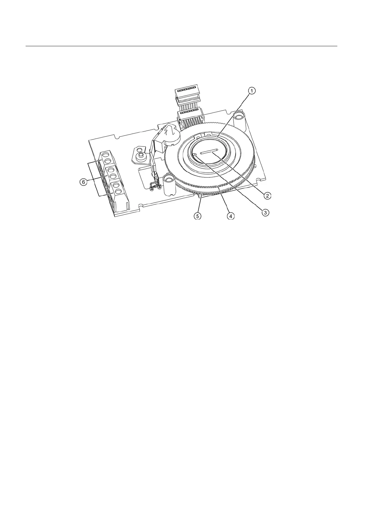
Upper actuating disk for limit L1, terminals 41/42
Lower actuating disk for limit L2, terminals 51/52
Figure 4-14 SIA module
The slotted initiator alarm unit, short SIA module, consists of three binary outputs ⑥.
You are familiar with the general procedure described in the chapter "Installing optional
modules in the standard and intrinsically safe version (Page 49)".
Procedure for installing the slot initiator alarm module
1. Disconnect all electrical connections of the basic electronics.
2. Loosen the two fixing screws of the basic electronics.
3. Disengage the basic electronics by carefully bending the four brackets.
4. Insert the SIA module from the top up to the upper printed circuit board guide of the rack.
5. Slide the SIA module in the printed circuit board of the rack approximately 3 mm to the
right.
6. Screw in the special screw ② through the SIA module into the positioner shaft. Tighten
the special screw
② with a
.
 Loading...


