Direction Determination with Negative Sequence System
Here, the negative sequence current and as reference voltage the negative sequence voltage are used for the
direction determination. This is advantageous if the zero sequence is influenced via a parallel line or if the zero
voltage becomes very small due to unfavorable zero impedances. The negative sequence system is calculated
from the individual voltages and currents. As with the use of the zero sequence values, a direction determina-
tion is carried out if the values necessary for the direction determination have exceeded a minimum threshold.
Otherwise the direction is undetermined.
When voltage transformers are open-delta-connected, direction determination is always based on the nega-
tive- sequence quantities.
Cross-Polarized Reference Voltages for Direction Determination
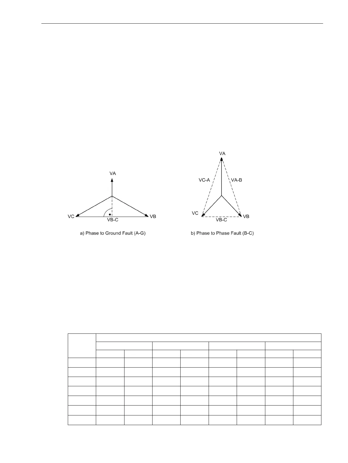
The direction of a phase-directional element is detected by means of a cross-polarized voltage. In a phase-to-
ground fault, the cross-polarized voltage (reference voltage) is 90° out of phase with the fault voltages (see
Figure 2-25). With phase-to-phase faults, the position of the reference voltages changes, depending on the
degree of collapse of the fault voltages, up to 30°.
[kurzschlussfremde-spannungen-fuer-richtungsbestimmung-260602-kn, 1, en_US]
Figure 2-25 Cross-polarized voltages for direction determination
Measured Values for the Determination of Fault Direction
Each phase has its own phase measuring element. The fourth measuring element is used as ground measuring
element. If the current exceeds the pickup threshold of a phase or that of the ground path, direction determi-
nation is started by the associated measuring element. In case of a multiphase fault, all phase measuring
elements involved perform their own direction determination. If one of the calculated directions differs from
the set direction, the function picks up.
The following table shows the allocation of measured values for the determination of fault direction for
various causes of pickup.
Table 2-6
Measured Values for the Determination of Fault Direction
Pickup Measuring element
A B C ground
Current Voltage Current Voltage Current Voltage Current Voltage
A
Ι
A
V
B
- V
C
— — — — — —
B — —
Ι
B
V
C
- V
A
— — — —
C — — — —
Ι
C
V
A
- V
B
— —
N — — — — — —
Ι
N
V
N
1)
A, N V
B
- V
C
— — — —
Ι
N
V
N
1)
B, N — —
Ι
B
V
C
- V
A
— —
Ι
N
V
N
1)
C, N — — — —
Ι
C
V
A
- V
B
Ι
N
V
N
1)
Functions
2.3 Directional Overcurrent Protection 67, 67N
SIPROTEC 4, 7SJ80, Manual 91
E50417-G1140-C343-A8, Edition 12.2017
 Loading...


