Pickup Measuring element
A B C ground
Current Voltage Current Voltage Current Voltage Current Voltage
A, B
Ι
A
V
B
- V
C
Ι
B
V
C
- V
A
— — — —
B, C — —
Ι
B
V
C
- V
A
Ι
C
V
A
- V
B
— —
AC
Ι
A
V
B
- V
C
— —
Ι
C
V
A
- V
B
— —
A, B, N
Ι
A
V
B
- V
C
Ι
B
V
C
- V
A
— —
Ι
N
V
N
1)
B, C, N — —
Ι
B
V
C
- V
A
Ι
C
V
A
- V
B
Ι
N
V
N
1)
A, C, N
Ι
A
V
B
- V
C
— —
Ι
C
V
A
- V
B
Ι
N
V
N
1)
A, B, C
Ι
A
V
B
- V
C
Ι
B
V
C
- V
A
Ι
C
V
A
- V
B
— —
A, B, C, N
Ι
A
V
B
- V
C
Ι
B
V
C
- V
A
Ι
C
V
A
- V
B
Ι
N
V
N
1)
1)
or 3 · V
0
= |V
A
+ V
B
+ V
C
|, depending on the connection type of voltages
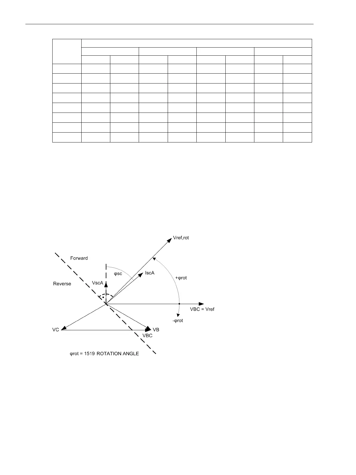
Direction Determination of Directional Phase Elements
As already mentioned, the direction determination is performed by determining the phase angle between the
fault current and the reference voltage. In order to satisfy different network conditions and applications, the
reference voltage can be rotated by an adjustable angle. In this way, the vector of the rotated reference
voltage can be closely adjusted to the vector of the fault current in order to provide the best possible result for
the direction determination. Figure 2-26 clearly shows the relationship for the directional phase element
based on a single-phase ground fault in Phase A. The fault current Ι
scA
follows the fault voltage by fault angle
ϕ
sc
. The reference voltage, in this case V
BC
for the directional phase element A, is rotated by the setting value
1519 ROTATION ANGLE, positively counter-clockwise. In this case, a rotation by +45°.
[7sj6x_drehung-referenzspannung-phase-200904-he, 1, en_US]
Figure 2-26 Rotation of the reference voltage, directional phase element
The rotated reference voltage defines the forward and reverse area, see Figure 2-27. The forward area is a
range of ±86° around the rotated reference voltage V
ref,rot
If the vector of the fault current is in this area, the
device detects forward direction. In the mirrored area, the device detects reverse direction. In the intermediate
area, the direction result is undefined.
In a network, the vector of the fault current is usually in the forward or reverse area. If the vector moves out of
one these areas, e.g. the forward area, in direction of the undefined area, it leaves the forward area at V
ref,rot
±86° and reaches the undefined area. If the vector leaves the undefined area in direction of the forward area
Functions
2.3 Directional Overcurrent Protection 67, 67N
92 SIPROTEC 4, 7SJ80, Manual
E50417-G1140-C343-A8, Edition 12.2017

 Loading...


