SWT 3000 Equipment Manual PU3 Module
© SIEMENS AG 2008 Edition p3_3_x 08/09 Page - 13
The digital line equipment DLE
The digital line interfaces LID-1 and LID-2 of the SWT 3000 system are implemented on module
DLE. These enable the protection commands (CMD) to be transmitted over a digital network
(SDH/PDH). The data for the Remote Maintenance (RM) and Service Channel (SC) interfaces and
the system-internal control information (CTRL) are transmitted additionally.
Module DLE is designed as a self-contained PC board connected electrically to the PU3 via a rib-
bon cable and mechanically via spacer sleeves. All external interfaces are routed via the PU3
module.
The following hardware interfaces are available for each LID:
z X.21 (64 kbit/s)
z G703.1 (64 kbit/s)
z G703.6 (2Mbit/s)
The LID-1 can be operated alone or the LID-1 and LID-2 jointly (for multipath transmission) on the
DLE. With multipath transmission different line interfaces can be used for LID-1 and LID-2.
Multipath transmission can also be implemented by using the analog in-
terface LIA on the PU3, and LID-1.
Transmission concept
On the DLE a data stream is generated at the transmit end from the protection commands, RM,
SC and the internal control information that is sent cyclically in 4 message types. There are split up
again at the receive end into protection commands, RM SC and control information.
The messages have the following priority among one another:
Type 3 Command information = Prio 1
Type 2 Service channel (SC)
Type 1 Remote maintenance (RM)
Type 0 Internal control information
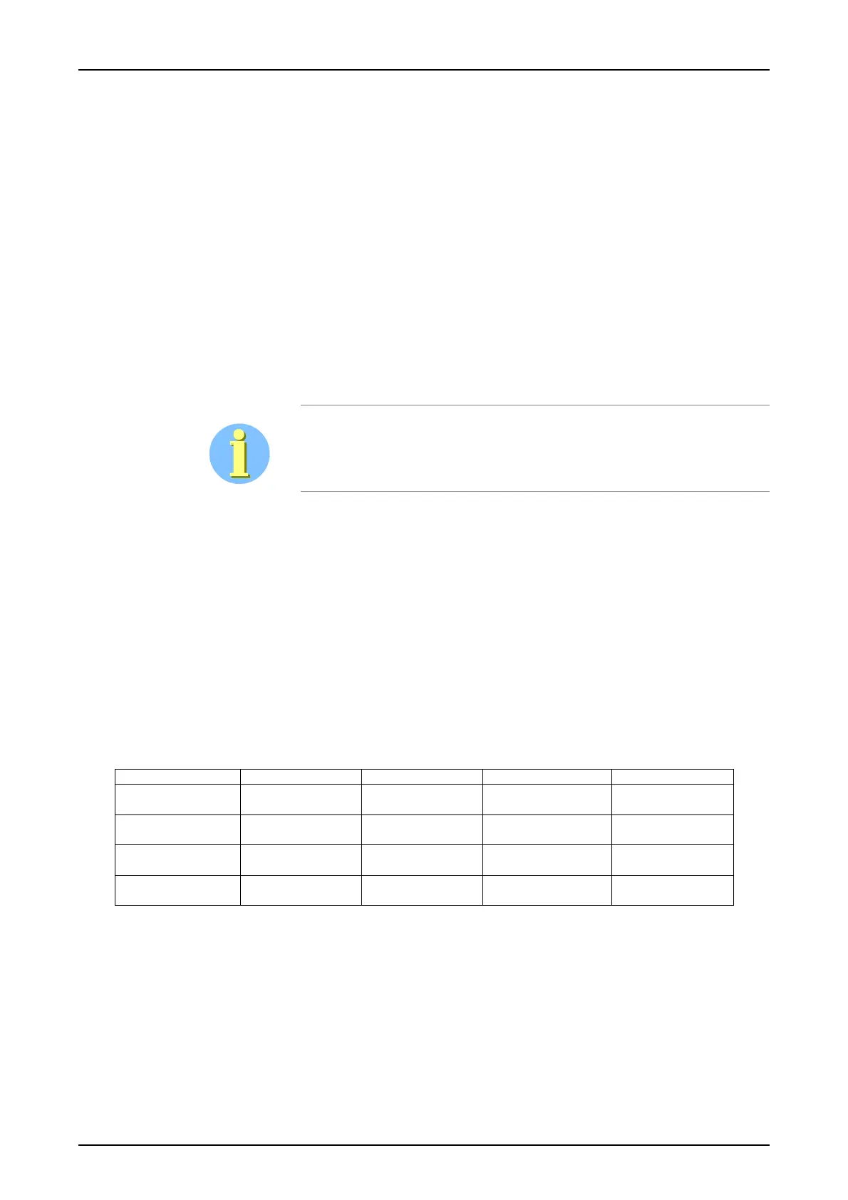
Messages have a constant length of 40 bits and are composed as follows:
Table 6: Message structure for the digital line interfaces
Byte 1 Byte 2 Byte 3 Byte 4 Byte 5
Frame alignment
signal
Type code 0 User data User data User data
Frame alignment
signal
Type code 1 RM data RM data RM data
Frame alignment
signal
Type code 2 SC data SC data SC data
Frame alignment
signal
Type code 3 Device address Command informa-
tion
Check sum