PU3 Module SWT 3000 Equipment Manual
Page - 14 Edition p3_3_2x 08/09 © SIEMENS AG 2008
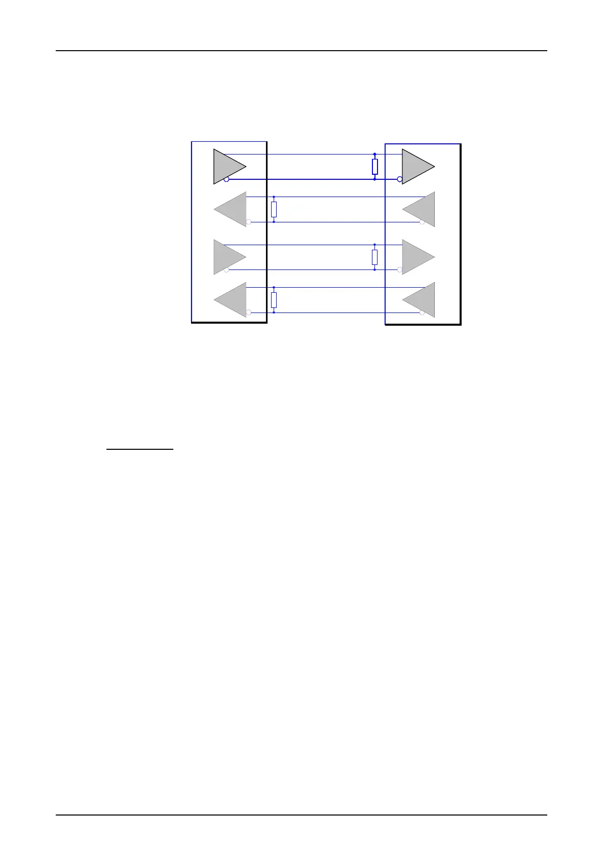
Line interface X.21
The X.21 interface is structured according to the RS422 standard (ITU-T V.11) and consists of the
data lines TxD and RxD and the clock lines TxC and RxC.
DTE
DTE
TxD (A)
TxD (B)
RxD (A)
RxD (B)
TxC (A)
TxC (B)
RxD (A)
RxD (B)
TxD (A)
TxD (B)
RxC (B)
RxC (A)TxC (A)
RxC (B)
RxC (A)
TxC (B)
TxC (A)
Figure 9: Structure of the line interface X.21
The high transmission reliability of the interface is achieved by evaluating the differential voltage
between a twisted wire pair in each case. The electrical levels of the data lines are defined with
0.3 V to -6 V for “logic 1“ and with +0.3 V to +6 V for “logic 0“. The signal state is identified by the
voltage between the measuring points (A) and (B).
Terminations of 100 ohms at the receiver inputs not only prevent reflections on the transmission
line, but also contribute to transmission reliability through the resulting pronounced current.
Characteristics
:
Number of signal lines: 8 (for each balanced pair for data and clock pulse, for transmit and re-
ceive direction in each case)
Levels: max. voltage of each line to GND (absolute) < 6V, differential voltage be-
tween the lines >2V
Line run: twisted in pairs and shielded, joint shield for all 4 line pairs
Bit rate: 64 kbit/s