Interface Modules SWT 3000 Equipment Manual
Page - 6 Edition p3_3_2x 08/09 © SIEMENS AG 2008
Controller
A controller is used on all interface modules for the following functions:
z Control of the data traffic from/to the PU3
z Sampling the signal inputs 1 to 4 and triggering an interrupt at the PU3 in case of
changes.
z Switching the command relays via the signal outputs.
z Supervision functions
The controller is connected to the PU3 controller via an internal bus.
Test input
Commands can be entered for each input in test operation by means of the DIL switches S1.1 to
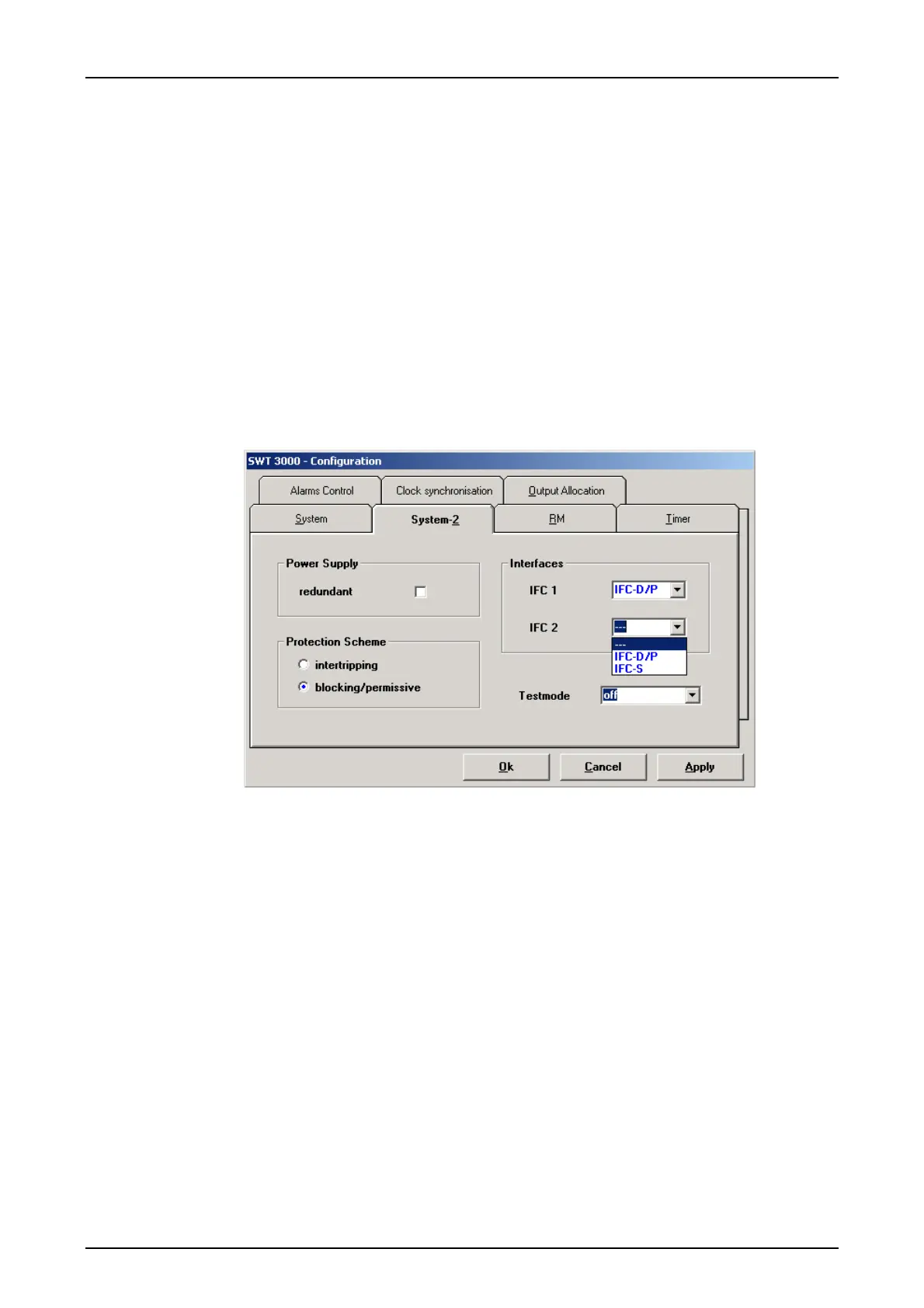
S1.4. Switchover from normal to test mode is effected with the service program SysWin 2000 under
SWT 3000 <System-2 configuration>.
Figure 4: The <System-2 configuration> tab
For security reasons the controller signals all inputs as “off“ after switching over to test mode re-
gardless of the actual switch position. The “on” state can only be reached by switching from posi-
tion “off” to “on”. All switches must be in the “off“ position beforehand.
Displays
The activated output relays are displayed with LEDs H1 to H4 (green), and the activated binary
inputs with LEDs H5 to H8 (green).