SWT 3000 Equipment Manual Installation and Commissioning
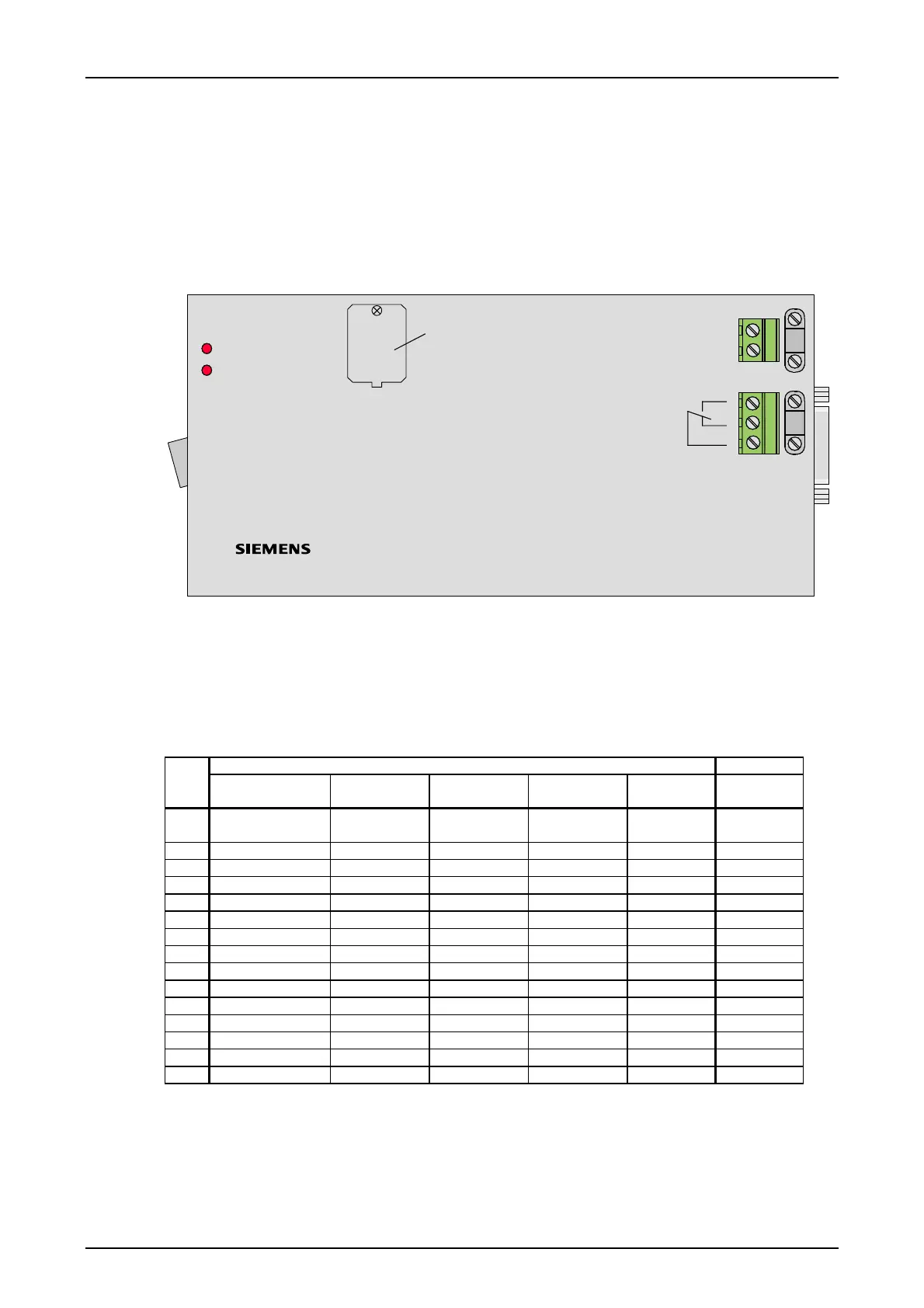
The FOBox
The FOBox is used for connecting the SWT 3000 via optical fibre with a PDH- or SDH-Multiplexer.
For each transmission direction a separate fibre is necessary. The FO Box contains the FOM mod-
ule with the electrical/optical conversion, the interface to the multiplexer and a power supply. Fur-
ther details are described in chapter 1 of this manual.
An adaptor is installed for the conversion from the system connector to the alarm relay, the con-
nectors for the digital interface (X.21/G703.1/G703.6) and the power supply connector.
X4
X2
X1
Alarm relay
+
1
2
3
Power supply
20-72V DC
22-60V AC
Imax=0,6A
Selection of the
digital Interface
Tx - Alarm
Rx - Alarm
FO Connection
-
1
2
X.21
G703.1
G703.6
Figure 13: The fibre optic box
Interfaces of the FOBox
The interfaces of the FOBox will be carried out by an adapter converting the pinning of the FOB
module to a 15-pin female Sub-D connector according the subsequent table.
Table 27: Pinning of the Sub-D female connector X1
DTE FOB-X11
Pin Function X.21 Name X.21 Name
G.703.1
Name
G703.6
Signal
Direction
Pin
1 Shield GNDS Shield Shield --- A1,A31,C1,
C31
2 Transmit(a) TxD_A TX- TX- OUT A12
3 Control(a) C(a) OUT A10
4 Receive(a) RxD_A RX- RX- IN A13
5 n.c.
6 Signal Timing(a) RxC_A IN A11
7 n.c.
8 Signal Ground GND G G --- A3
9 Transmit(b) TxD_B TX+ TX+ OUT A8
10 Control(b) C(b) OUT A14
11 Receive(b) RxD_B RX+ RX+ IN A9
12 n.c.
13 Signal Timing(b) RxC_B IN A15
14 n.c.
15 n.c.
© SIEMENS AG 2008 Edition p3_3_2x 08/09 Page - 25