Installation and Commissioning SWT 3000 Equipment Manual
PC Connecting cable
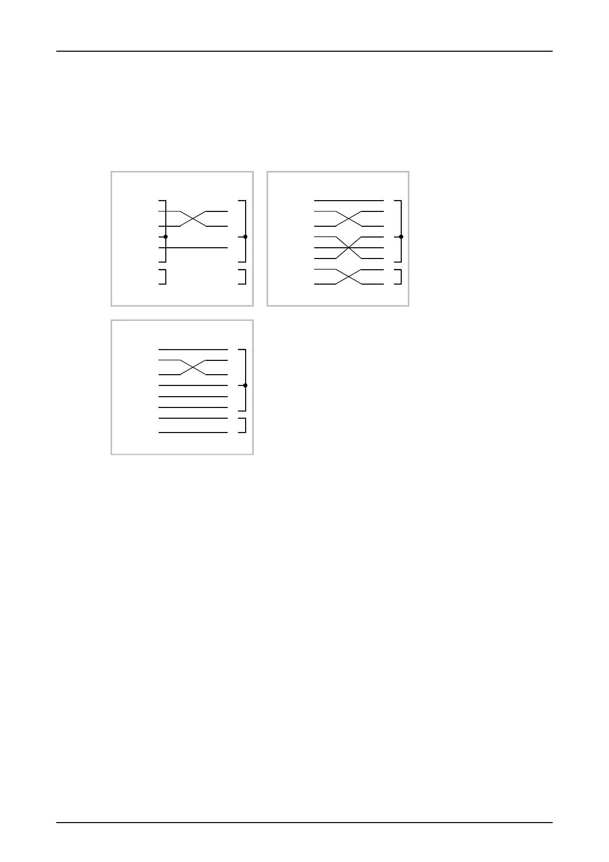
The following diagrams show the possible variants for cable connections between the control PC
and the interface on the SWT 3000 front panel. Terminals 1-4-6 and 7-8 are connected at this
socket.
1
2
3
4
5
6
7
8
9
CD
RD
TD
DTR
SG
DSR
RTS
CTS
RI
1
2
3
4
5
6
7
8
9
1
2
3
4
5
6
7
8
9
CD
RD
TD
DTR
SG
DSR
RTS
CTS
RI
1
2
3
4
5
6
7
8
9
1
2
3
4
5
6
7
8
9
CD
RD
TD
DTR
SG
DSR
RTS
CTS
RI
1
2
3
4
5
6
7
8
9
PC (com_x) PU3 PC (com_x) PU3
PC (com_x) PU3
CD Common Data
RD Receive Data
TD Transmit Data
DTR Data Terminal Ready
SG Signal Ground
DSR Data Set Ready
RTS Request To Send
CTS Clear
To Send
RI Incoming call
Figure 17: Possible cable variants for the connection of the service PC
Page - 32 Edition p3_3_2x 08/09 © SIEMENS AG 2008