CLE Module SWT 3000 Equipment Manual
Page - 4 Edition p3_3_x 08/09 © SIEMENS AG 2008
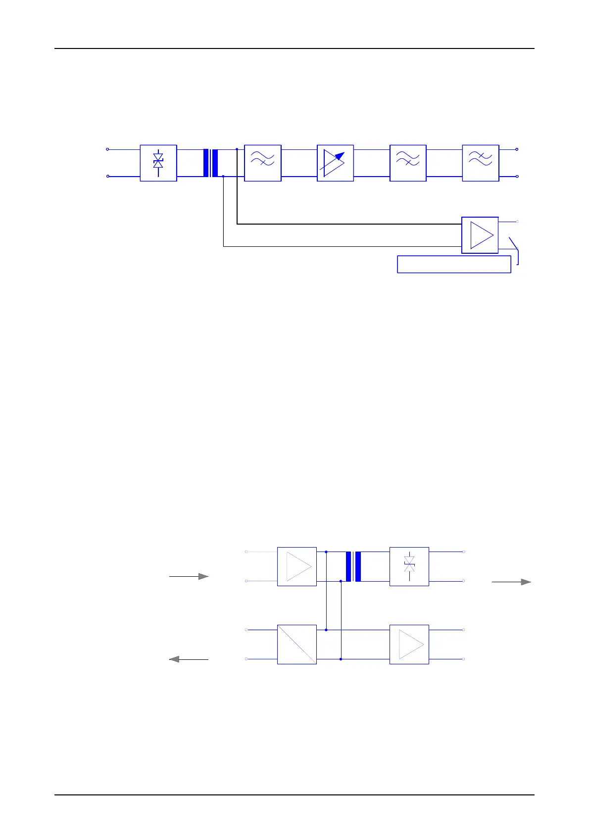
The receive section
The incoming VF signal from the copper line or from a PLC system is fed in at the receive section.
The input is protected against overvoltages up to 2kV that may be transferred to the transmission
route by coupling. The input impedance can be switched over from 600 Ω to approx. 5 kΩ.
Z=600Ω
Ω
Z=600Ω
5 k
Figure 2: The input circuit of the CLE module
The wanted signal is then filtered out from any interference signals. The attenuation tolerance dia-
gram of a band pass filter is preset for the input filter. The pass band is from 500-4000 Hz. The
band pass filter is implemented by cascading an active low-pass and high-pass filter.
The forward amplifier can be set to 0dB/+6dB/+12dB by means of links. Greater immunity to 50
Hz interference is obtained by means of the series-connected high-pass filter.
The signal is then transferred to the PU3. The receive signal can be tapped at a test socket. The
test socket is decoupled via an isolating amplifier so that there is no interference of the wanted sig-
nal through short-circuits or insertion of signals. The same voltage level prevails at the test socket
as at the input. The settable thresholds for the level alarm relate to the input of the PU3 and not to
the input of the CLE.
The transmit section
The wanted signal supplied by the PU3 is amplified in the transmit section. There is no filtering as
there is in the receive section since the signal supplied does not have interference of this type. The
PU3 supplies a level up to +4dB. The input signal is amplified by 11 dB to the range up to +15 dB.
The signal is extracted without voltage via a transformer with winding ratios that can be set to 1:2
or 1:16 and matched to the output impedance. This can be set to 600 Ω or 5 kΩ by means of links
with the corresponding output circuit.
Z=600
5k
Ω
Ω
Z=600Ω
Z=5k
Ω
DC
RMS
c11
c13
Figure 3: Block diagram of the transmit amplifier
The output of the transmit section is again protected against any interference voltages from the
transmission path. The wanted signal can be measured via an isolating amplifier. A measuring
transformer supplies a DC voltage level that is proportional to the amplitude of the output signal to
the PU3 module for test purposes. The PU3 monitors this measured value and generates the
transmitter alarm from it. The output voltage for the 100% value is 4.5 V. A protective circuit re-
stricts this voltage to max. +5V.
from the PU3
to the measuring input
of the PU3
Amplifier +11 dB
Isolating ampl.
Protection circuit
Test socket
to the trans-
mission line
Protective circuit
HP filter passive Isolating amplifier HP filter active
LP filter active
Isolating amplifier
Test socket