Functional Description SWT 3000 Equipment Manual
Page - 38 Edition p3_3_2x 08/09 © SIEMENS AG 2008
Power supply
Stand-alone unit
One or alternatively two power supplies can be used in the SWT 3000 system. They are decoup-
led via diodes on the rear PC board. The output voltages from SV-1 and SV-2 are monitored by the
PU3 module in order to detect failure of a power supply.
The interface modules IFC are supplied via the PU3.
If two power supplies are used the SWT 3000 sub rack can only be
equipped with one unit.
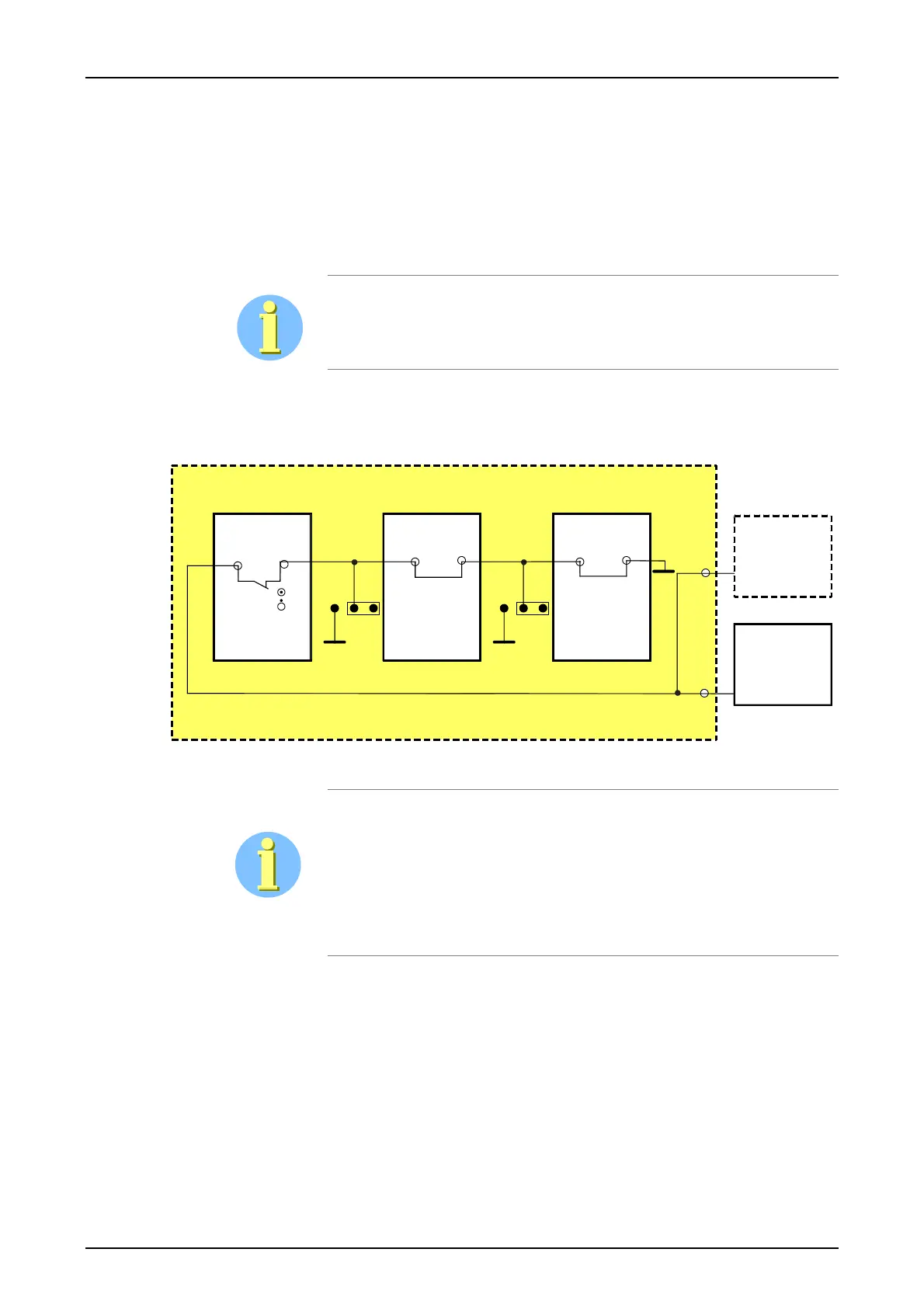
Monitoring loop The presence of the PU3 and CLE modules is monitored by an Inhibit
loop. If the PU3 and/or CLE is pulled, this interrupts the monitoring loop
and the secondary voltages from SV-1 and SV-2 (if present) are discon-
nected.
PU3e
CLE/FOM1
SV1
SV2
a21
c21
a21
c21
GND
BPSWT 3000
GND
1
23
X41
SV
FOM2
a21
c21
GND
1
23
X42
Figure 19: Inhibit loop for the power supply(ies)
An On/Off switch (SV) on the PU3 (not accessible from outside) also in-
terrupts this monitoring loop.
If only the CLE resp FOM1 module is not used the jumper X41 must be
inserted in position 1-2.
If the FOM2 is not used the jumper X42 must be in position 1-2.
Integrated unit
If the SWT 3000 is used in the PowerLink (iSWT) system the PU3 unit is supplied via the central
power supply of the PowerLink. The IFC modules are supplied via the PU3 again.