SWT 3000 Equipment Manual Installation and Commissioning
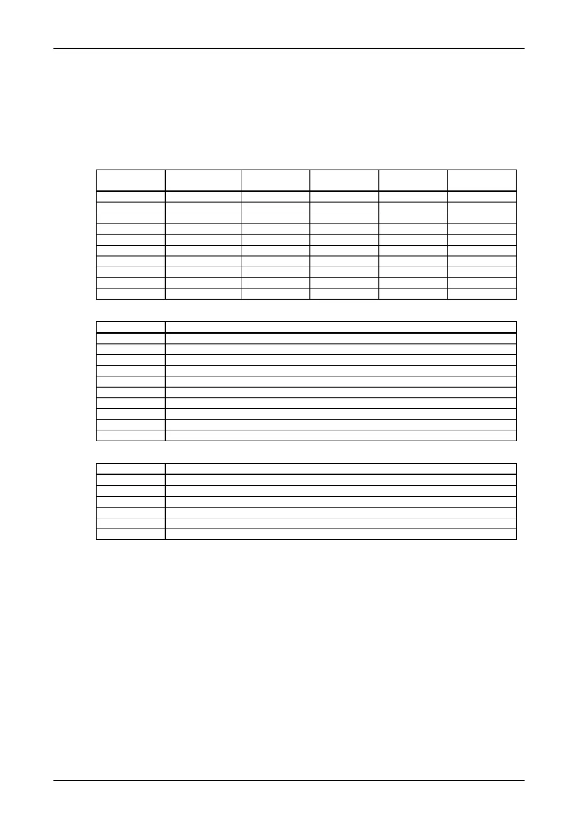
The socket assignment can be seen from the following tables.
Signals for the LID-1 (Line Interface Digital 1)
The signals for digital line interface 1 are fed from PU3f via the SUB-D plug X1 to the backplane
of the device. The pin assignment depends on the interface used.
Table 6: Pin assignments for interface LID-1
Terminal PU3f
cable connector
SUB-D plug X1
Pin
Module X.21
Signal
Module G703.1
Signal
Module G703.6
Signal
LID_11 a8 4 X21_RxD_A1 DI11 DI11
LID_12 c8 11 X21_RxD_B1 DI12 DI12
LID_13 a9 2 X21_TxD_A1 DO11 DO11
LID_14 c9 9 X21_TxD_B1 DO12 DO12
LID_15 a10 6 X21_RxC_A1
LID_16 c10 13 X21_RxC_B1
LID_17 a11 7 X21_TxC_A1
LID_18 c11 14 X21_TxC_B1
GNDS /Shield a31 c31 1 GNDS / Shield GNDS GNDS
GND / Signal a3 c3 8 GND / Signal GND GND
Table 7: Signals for the X-21 interface for LID-1
Signal name Function
X21RDA1 Input: X.21 Receive data signal a
X21RDB1 Input: X.21 Receive data signal b
X21TDA1 Output: X.21 Transmit data signal a
X21TDB1 Output: X.21 Transmit data signal b
X21RCA1 Input: X.21 Receive clock signal a
X21RCB1 Input: X.21 Receive clock signal b
X21TCA1 Output: X.21 Transmit clock signal a
X21TCB1 Output: X.21 Transmit clock signal b
GNDS Shielding
GND Signal reference potential
Table 8: Signal for the G703.1 and G703.6- interface for LID-1
Signal name Function
DI11 Input: Data in signal 1
DI12 Input: Data in signal 2
DO11 Output: Data out signal 1
DO12 Output: Data out signal 2
GNDS Shielding
GND Signal reference potential
© SIEMENS AG 2008 Edition p3_3_2x 08/09 Page - 15