Installation and Commissioning SWT 3000 Equipment Manual
Signals of the line interface analog (LIA)
Table 5: Pin assignment for interface LIA
Pin PU3f X1 Signal
b28 Input: F6 signal in IF1 range from HFE
b29 Reference potential for F6 signal IF1 range from HFE
a29 Output: F6 signal in IF1 range to the HFS
c30 Reference potential for F6 signal IF1 range to the HFS
b26 Output: F6 signal in VF range to the IF_transmission module
b27 Reference potential for F6 signal in VF range to the IF_ transmission module
b24 Input: F6 signal in VF range from the IF_receiver module
b25 Reference potential for F6 signal in VF range from the IF_receiver module
b23 Output: Control signal S6 for WZ operation to the IF_transmission module
a3, b3, c3, a20,
b22, c22
Signal reference potential GND
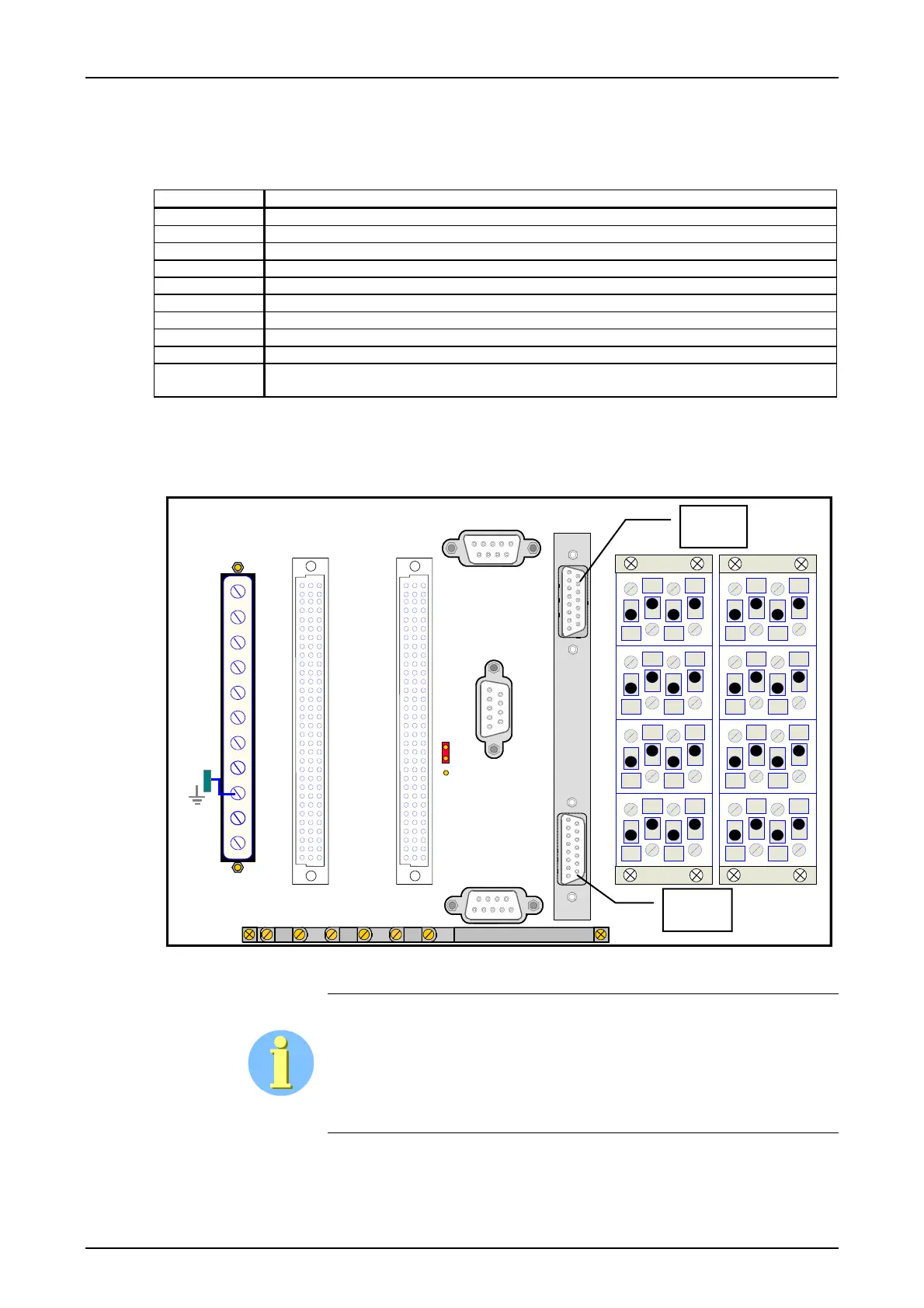
Connection of the digital line interfaces
The signals at the digital interfaces are fed via a plug connector from the PU3f to the SUB-D
sockets X1 (LID-1) and X2 (LID-2).
1
2
3
4
1
2
3
4
1
2
3
4
1
2
3
4
1
2
3
4
1
2
3
4
1
2
3
4
1
2
3
4
N(+)
X1
L1(-)
SV
2
5
8
11
14
17
20
23
26
29
32
ALRS
X2
CLE
X3
C1
A1
C1
A1
C32
A32
C32
A32
C32
A32
C1
A1
IFC-1
IFC-2
X41
X4
PU3
X1
X2
SSB
SC
SSR
Figure 7: Connection sockets X1 and X2 for the digital interfaces
Every wire pair in the connecting cables used for the digital interfaces
should be twisted and shielded.
Minimum requirements:
Every wire pair twisted and complete shielding for all wire pairs.
LID-1
LID-2
Page - 14 Edition p3_3_2x 08/09 © SIEMENS AG 2008