Installation and Commissioning SWT 3000 Equipment Manual
Signals for LID-2 (Line Interface Digital 2)
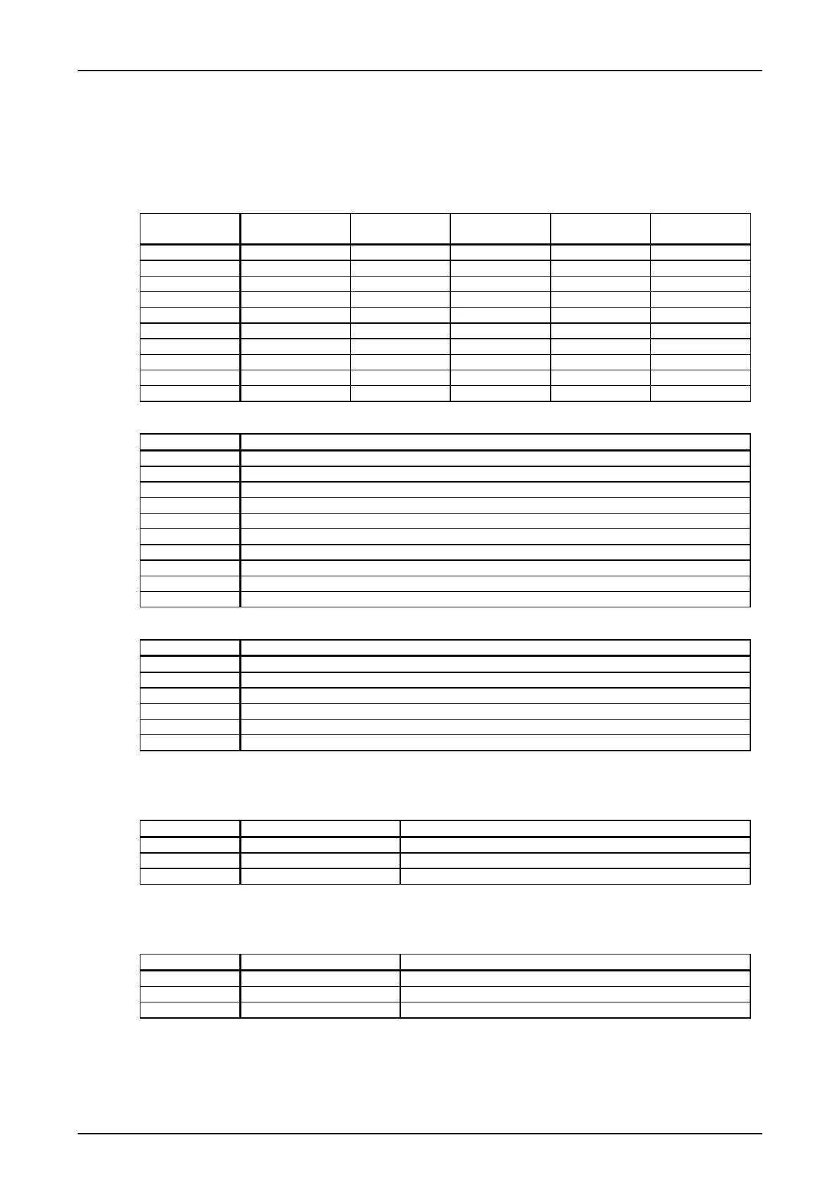
The signals for digital line interface 2 are fed from the PU3f via the SUB-D plug X2 to the back-
plane of the device. The pin assignment depends on the interface used.
Table 9: Pin assignments for the LID-2
Terminal PU3f
cable connector
SUB-D plug X2
Pin
Module X.21
Signal
Module G703.1
Signal
Module G703.6
Signal
LID_21 a12 4 X21_RxD_A2 DI21 DI21
LID_22 c12 11 X21_RxD_B2 DI22 DI22
LID_23 a14 2 X21_TxD_A2 DO21 DO21
LID_24 c14 9 X21_TxD_B2 DO22 DO22
LID_25 b5 6 X21_RxC_A2
LID_26 b6 13 X21_RxC_B2
LID_27 b10 7 X21_TxC_A2
LID_28 b12 14 X21_TxC_B2
GNDS /Shield a31 c31 1 GNDS / Shield GNDS GNDS
GND / Signal a3 c3 8 GND / Signal GND GND
Table 10: Signals for the X-21 interface for LID-2
Signal name Function
X21RDA2 Input: X.21 Receive data signal a
X21RDB2 Input: X.21 Receive data signal b
X21TDA2 Output: X.21 Transmit data signal a
X21TDB2 Output: X.21 Transmit data signal b
X21RCA2 Input: X.21 Receive clock signal a
X21RCB2 Input: X.21 Receive clock signal b
X21TCA2 Output: X.21 Transmit clock signal a
X21TCB2 Output: X.21 Transmit clock signal b
GNDS Shielding
GND Signal reference potential
Table 11: Signals for the G703.1 and G703.6 interface for LID-1
Signal name Function
DI21 Input: Data in signal 1
DI22 Input: Data in signal 2
DO21 Output: Data out signal 1
DO22 Output: Data out signal 2
GNDS Shielding
GND Signal reference potential
Service channel interface SC
Table 12: Signals for the service channel interface
Signal name SC connector Pin Function
LID_SC_RX 2 Output: Service channel receive data
LID_SC_TX 3 Input: Service channel transmit data
GND 5 Signal reference potential
Remote access interface SSR
Table 13: Pin assignment of the remote access interface SSR
Signal name SSR connector Pin Function
RxD 2 Receive data
TxD 3 Transmit data
GND 5 GND
Page - 16 Edition p3_3_2x 08/09 © SIEMENS AG 2008