Installation and Commissioning SWT 3000 Equipment Manual
Pin assignments of the SWT 3000 modules:
Pin assignment of the IFC-x module
The IFC interface modules must be connected from the protective relay to connector X1 (modular
terminal block) (cable cross section up to 1.5 mm
2
). MINIMUM two cables have to be tied immedi-
ately at the terminals.
BI4BI3BI2BI1
CO1CO2 CO3 CO4
K9 K10 K11 K12
K5 K6 K7K8
4A
3A
2A
1A
1
2
3
4
1
2
3
4
1
2
3
4
1
2
3
4
IFC-D/P
CR
IFC-S
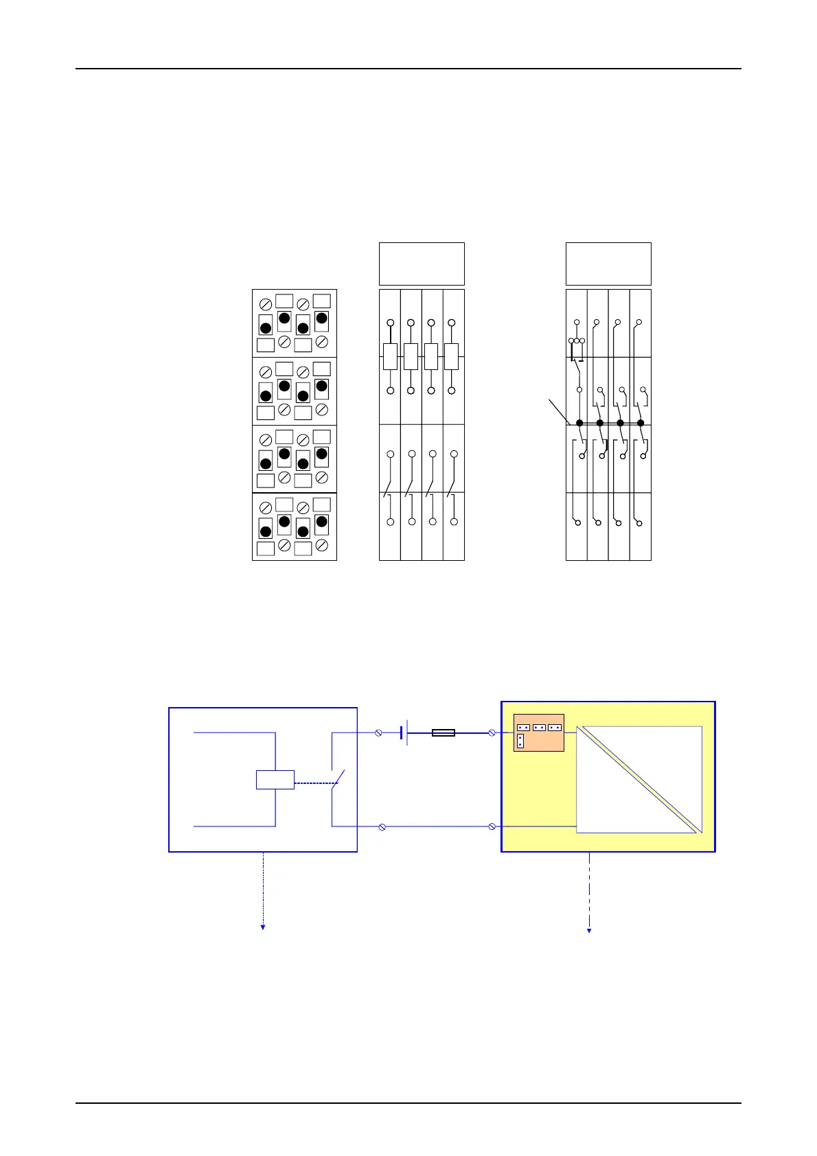
IFC-D Interface module for direct tripping BI1 -4 Binary inputs 1 to 4
IFC-P Interface module for permissive tripping CO1 - 4 Command outputs 1-4
IFC-S Interface module for signaling K5-8 Signaling of the binary inputs 1 to 4
CR Common root of relays K5 to K12 K9-12 Signaling of the command outputs
Figure 5: Contact assignment of the interface module IFC-x
The connection principle of the IFC-D/P binary inputs can be seen from the following diagram:
PR
IFC-D/P BI 1
U = 24...250 V
3A1
4A1
X45X44X43
X55
*)
F
*) Setting of the nominal input voltage
PR Protection relay
BI 1 Binary input 1
F Fuse
Figure 6: Connection principle for the binary inputs of the IFC-D/P modules
Page - 12 Edition p3_3_2x 08/09 © SIEMENS AG 2008