CLE Module SWT 3000 Equipment Manual
Page - 8 Edition p3_3_x 08/09 © SIEMENS AG 2008
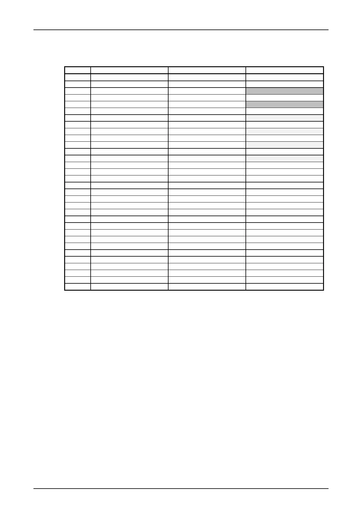
Connector pin assignment of the CLE
Table 3: Connector pin assignment of the CLE module
Pin Pin a Pin b Pin c
1 Shield GNDS GNDS
2
3 Ground GND Control wire S6 (S6AB)
4
5 Control wire S6 (S6AB_GND)
6
7 Protection receive signal A
8
9 Protection receive signal B
10
11 Protection transmit signal A
12
13 Protection transmit signal B
14
15 DC value transmit signal
16 S/N Alarm DC value transmit signal GND P5V (+5V)
17 EAL Alarm P5V (+5V)
18 P12V (+12V) M12V (-12V)
19 SAL Alarm
20 GND12 P12V (+12V)
21 INHIBIT INHIBIT
22 M12V (-12V) GND12
23 Enable transmitter output S6 control line from PU3
24 VF signal from PU3
25 VF signal from PU3 GND
26 VF signal to PU3
27 VF signal to PU3 GND Ground GND
28 S6 control wire from PU3
29
30
31 Shield GNDS Shield GNDS
32