Installation and Commissioning SWT 3000 Equipment Manual
Power supply of the FOBox
The supply voltage range is 20-72V DC or 22-60V AC
Table 28: Assignment of the X4 connector for the power supply
Pin Function
1 - 20-72 V DC
2 + 20-72 V DC
Alarm relay contacts of the FOBox
Table 29: Assignment of the X2 connector for the alarm output
Pin Function
1 alarm relay make contact
2 alarm relay break contact
3 alarm relay common contact
Signification of the LED
H1H9
H8
H4
H5
H7
H6
FOB
Programming
interface
DCDC
Converter
Tx - Alarm
Rx - Alarm
X12
X7X6X5
alarm
relay
loops
X8
X9
X2X3
X14
X19
X15
X16
X18
X17
H10
H11
11
1
1
1
1
1
1
1
1
data interface
selection
G703.6
coax/sym
G703.6
sym/coax
isolation test
b
i
t
r
a
t
e
2
M
/
6
4
k
G
7
0
3
.
1
/
X
.
2
1
D
C
E
/
D
T
E
1
1
1
1
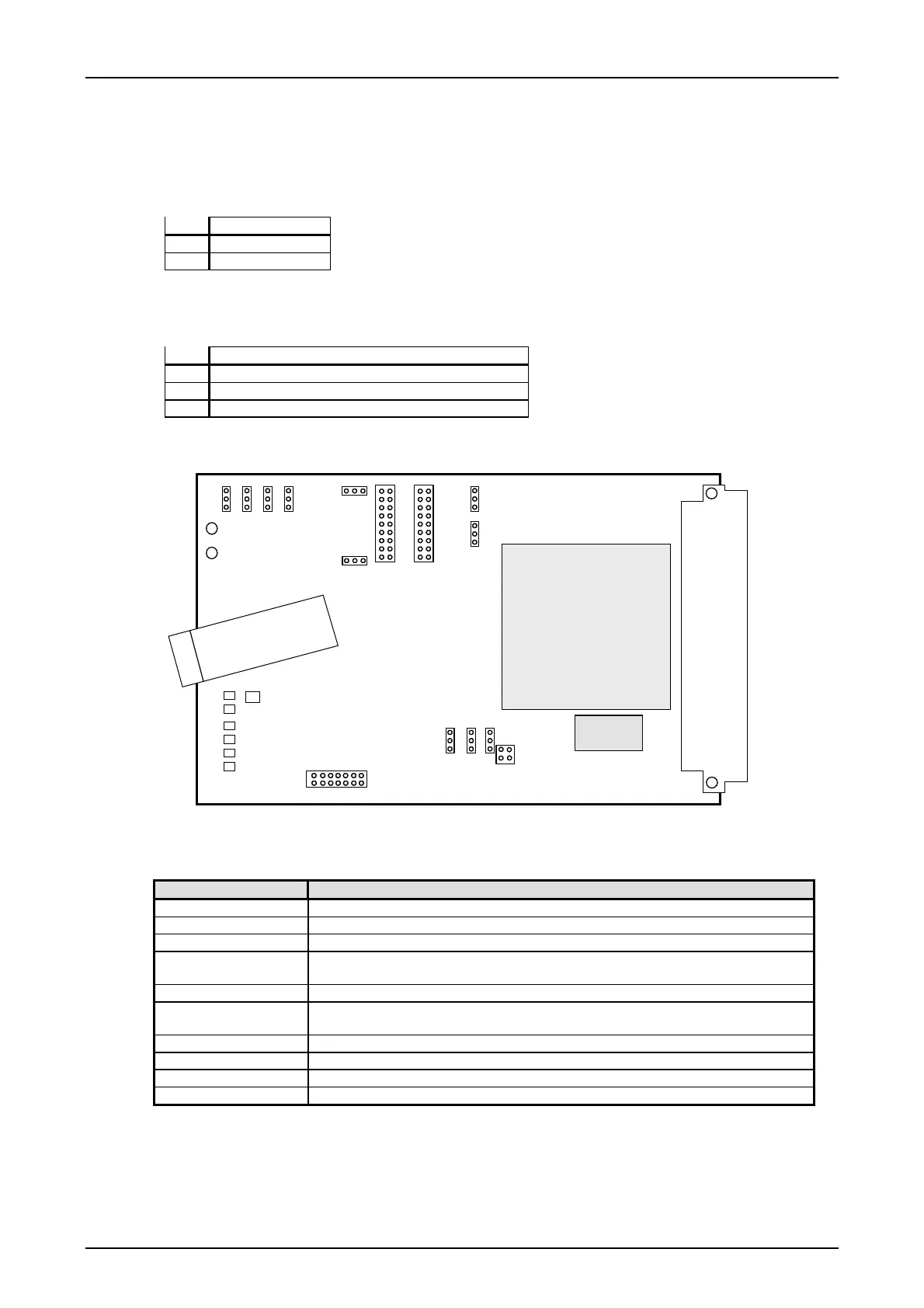
Figure 14: Position of the jumper and LED on the FOB module
Table 30: Signification of the alarm LED on the FOB
LED LED-indication when lit
H1 red FPGA not ready
H4 yellow - - -
H5 yellow BUF-alarm. Buffer overflow or under run. Source: Supervisory circuit of FPGA
H6 yellow MOD-alarm. Modulation alarm, carrier frequency at the optical receiver not
detected.
H7 yellow COM-alarm. Communication alarm at the electrical interface.
H8 yellow SFP_LOS. The received optical power is below the receiver sensitivity. Loss of
signal
H9 yellow - - -
H10 red RX-alarm. F6 supervisory alarm
H11 red TX-alarm
Page - 26 Edition p3_3_2x 08/09 © SIEMENS AG 2008