Installation and Commissioning SWT 3000 Equipment Manual
Jumper settings for the SWT 3000 modules:
Jumper settings for the IFC modules
X41
X54
K1
K2
K3
K4
K8
K7
K6
K5
K9
K10
K11
K12
K16
K15
K14
K13
X42
IFC-D: K1 . . . K4
IFC-P: K13 . . . K16
IFC-S: K5 . . . K12
X53
X52
X51
X50
X49
X48
X47
X46
X45
X44
X43
BI 1
BI 3
BI 4
BI 2
X58
X57
X56
X55
S1
H1 H5
H2
H3
H4
H6
H7
H8
H10
H9
Control logic
1
2
3
4
X30
X40
1
1
Test operation
display
Operating LED
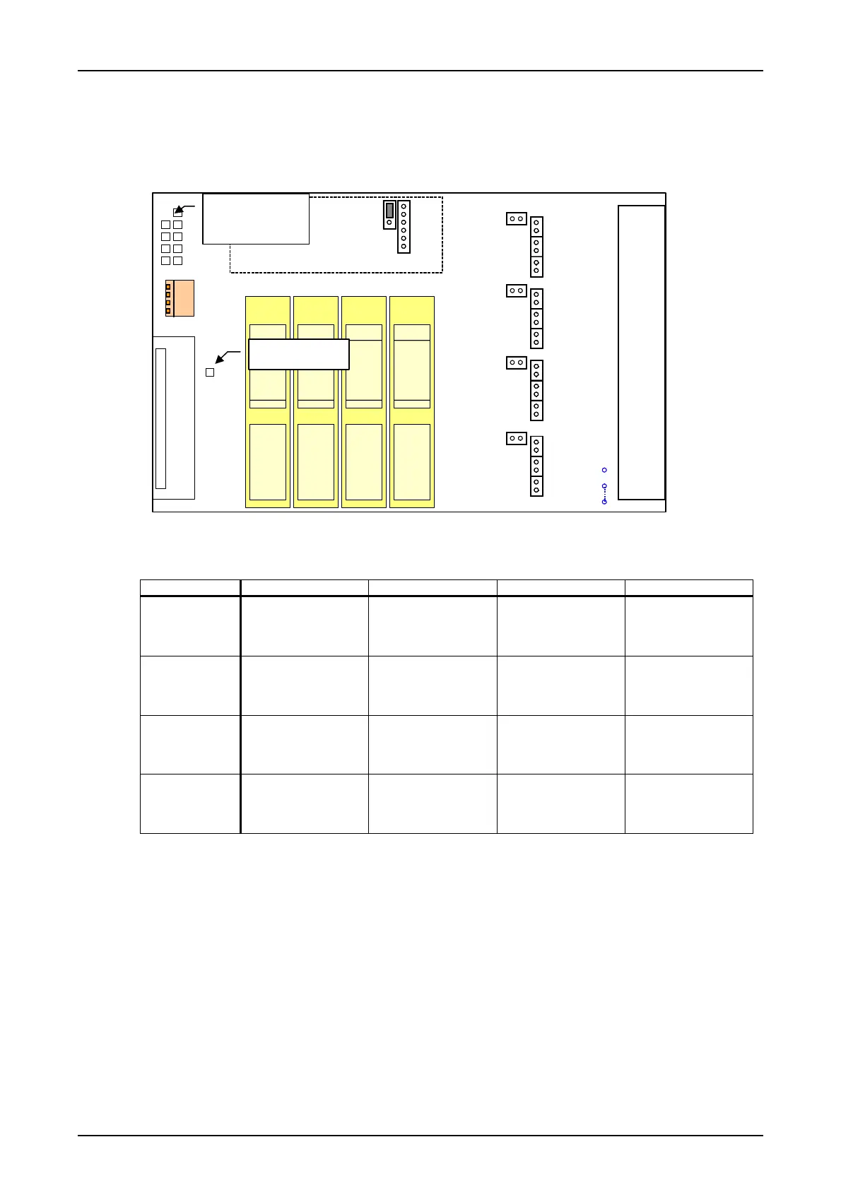
Figure 8: Position of jumpers X43 to X58
Table 19: Assignment of jumpers X43 to X58
Signal input 250V 110V 48/60V 24V
BI1
X55=inserted
X43=open
X44=open
X45=open
X55=open
X43=inserted
X44=open
X45=open
X55=open
X43=open
X44=inserted
X45=open
X55=open
X43=open
X44=open
X45=inserted
BI2
X56=inserted
X46=open
X47=open
X48=open
X56=open
X46=inserted
X47=open
X48=open
X56=open
X46=open
X47=inserted
X48=open
X56=open
X46=open
X47=open
X48=inserted
BI3
X57=inserted
X49=open
X50=open
X51=open
X57=open
X49=inserted
X50=open
X51=open
X57=open
X49=open
X50=inserted
X51=open
X57=open
X49=open
X50=open
X51=inserted
BI4
X58=inserted
X52=open
X53=open
X54=open
X58=open
X52=inserted
X53=open
X54=open
X58=open
X52=open
X53=inserted
X54=open
X58=open
X52=open
X53=open
X54=inserted
The second interface module is used in the case of an IFC-D/P module for doubling the output
contacts. The binary inputs are connected at only one module (in slot IFC-1).
In the case of module IFC-S jumpers X43- X58 are not provided because the binary inputs
are not existing. The module contains 8 signaling relays. For seven relays one changeover con-
tact is brought out in each case. The contact of relay K5 can be used as a make contact or a break
contact by means of jumper X42. All eight signaling contacts have a common root (3A1).
The jumper X30 serves for the switch over to the programming of the controller. In normal op-
eration the jumper must be in position 1-2. The connector X40 serves for the connection of the
programming device.
Page - 20 Edition p3_3_2x 08/09 © SIEMENS AG 2008