Page 72
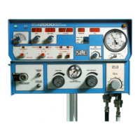
14.1.19 Flow sensor removal for suctioning or re-
calibration but continuing ventilation
If the user requires to keep the patient ventilated
whilst carrying out suctioning the following
procedure for circuit disconnection should be used.
Step 1. Remove the ET manifold from the flow
sensor.
Step 2. Remove the Flow sensor from the ET tube.
Step 3. Re-fit the ET manifold to the ET tube.
Step 4. Carry out procedure (example shown,
endotracheal suctioning).
Step 5. Remove the ET manifold from the ET tube.
Step 6. Re-fit the flow sensor to the ET tube.
Step 7. Re-fit the ET manifold to flow sensor.
14.1.20 BPM Tot. Measurement.
The ventilator measures BPM in two different ways,
with and without a flow sensor.
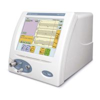
When used without a flow sensor, the ventilator
measures pressure in the proximal airway tube to
determine whether a breath has been delivered.
Because of this monitoring of pressure, the BPM
reading in the lung mechanics and measurement
panel, displays the total number of machine
delivered breaths (Mechanical breaths and
triggered breaths).
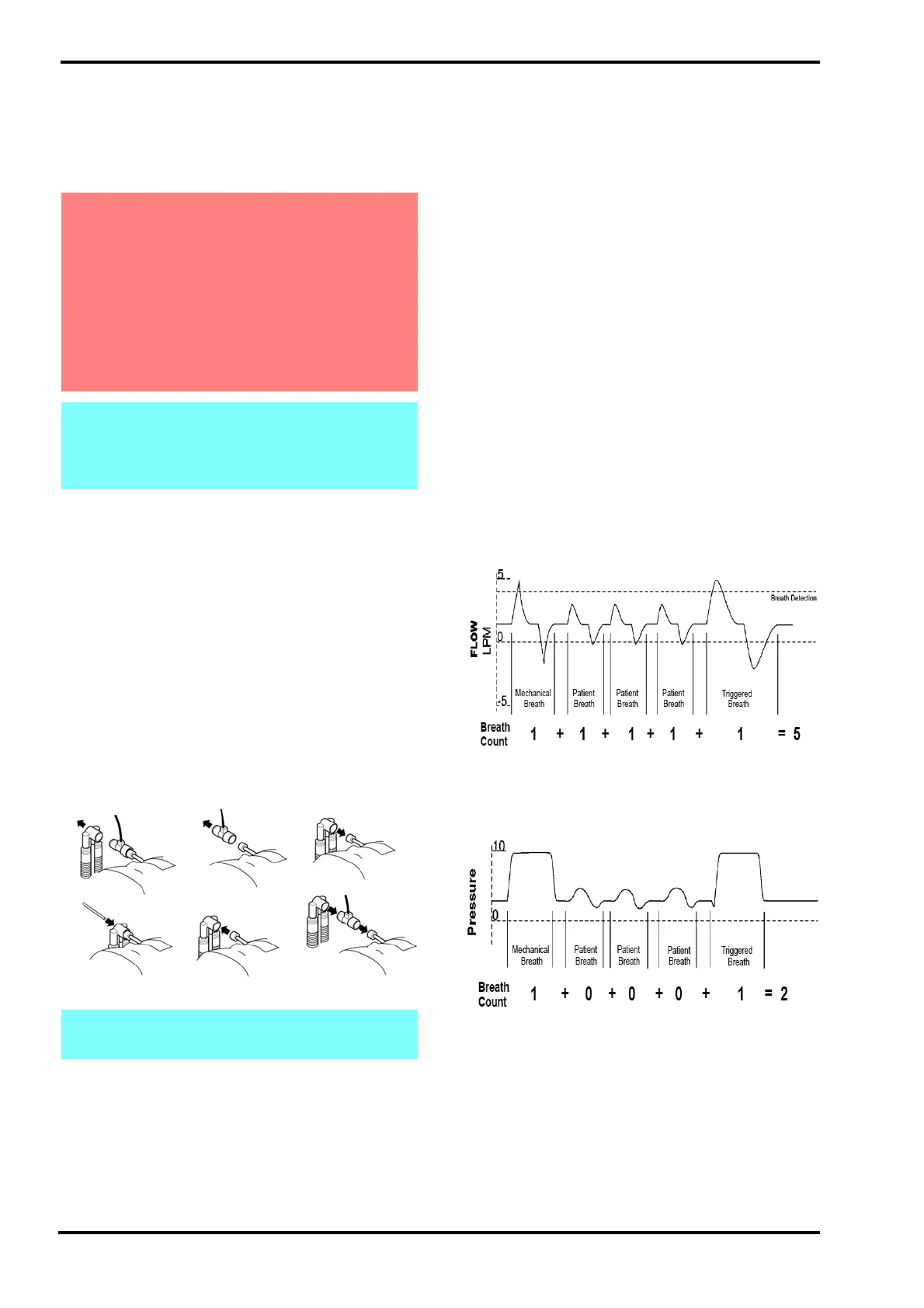
When used with a flow sensor, the ventilator is
measuring all the patient breaths based on the tidal
volume. The ventilator flow monitoring system
recognizes a breath as one inspiration followed by
one expiration.
In the lung mechanics and measurement panel the
BPM will be the total number of patient breaths.
Because of the monitoring of the tidal volume the
BPM total is made up of the total number of
mechanical breaths, triggered patient breaths and
any breaths that do not reach the set breath
detection level.
The above respiratory cycle would have only
registered 2 breaths with pressure monitoring as
shown below.
Warning. The user should set the MAX PIP
close to measured PIP (4 to 5 mbar above
measured PIP or as per clinical
recommendation). If the flow sensor is
removed from the circuit (for suctioning or re-
calibration) and the patient circuit is
reconnected, the ventilator senses that the
Vte has dropped below the set target level. It
will then increase the pressure up to the set
MAX PIP to try and achieve the set Vte.
Note: The user can pre-mute / mute the alarm
system as the ventilator will alarm during this
procedure. (The visual alarm indicator will
still be present).
Note: The user may have to re-adjust the MAX
PIP setting.
Step 1
Step 2
Step 3
Step 4
Step 5 & 6Step 5