105
• This value represents the adjustment value to be entered into the system - increments of 0.002 of an
inch or 0.05 mm.
• If the value is 0, then the system is calibrated for that axis - an entry is not required.
D. Slide the arrow on the screen to match where the support is most centered. Only move
arrows on two of the four sides of the calibration part.
E. Press O
K. The screen will pop up asking if you want to apply these values. Press OK. When
X and Y are both at 0, proceed to adjusting the Z.
F. If an adjustment entry for either axis is required, re-run the calibration model on a clean build
s
heet.
G. Continue to check and adjust for XY offset until the calibration toolpath is centered at 0 for
t
he X and Y axis.
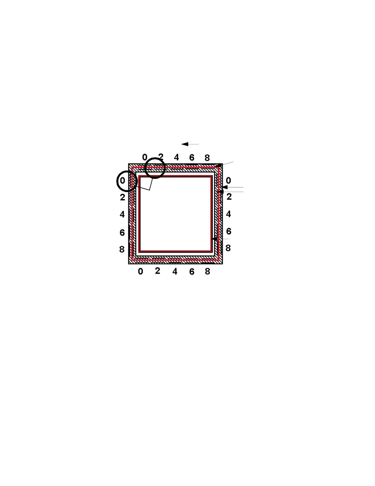
Figure 5-4: Ca
libration Model - English Units
H. After the adjustments are made, a new calibration box can be run from this menu by
p
ressing Build Calibration Box.
Tip Offset Adjustment Indicators
X - Y Support Calibration
Toolpath
X - Y Alignment
Indicators
Z Calibration Box
- Y
+ Y
+ X
Example: Best
Centered Position
This example requires
an adjustment to
Y of -.002 in. The X axis
requires no adjustment.
- X