106
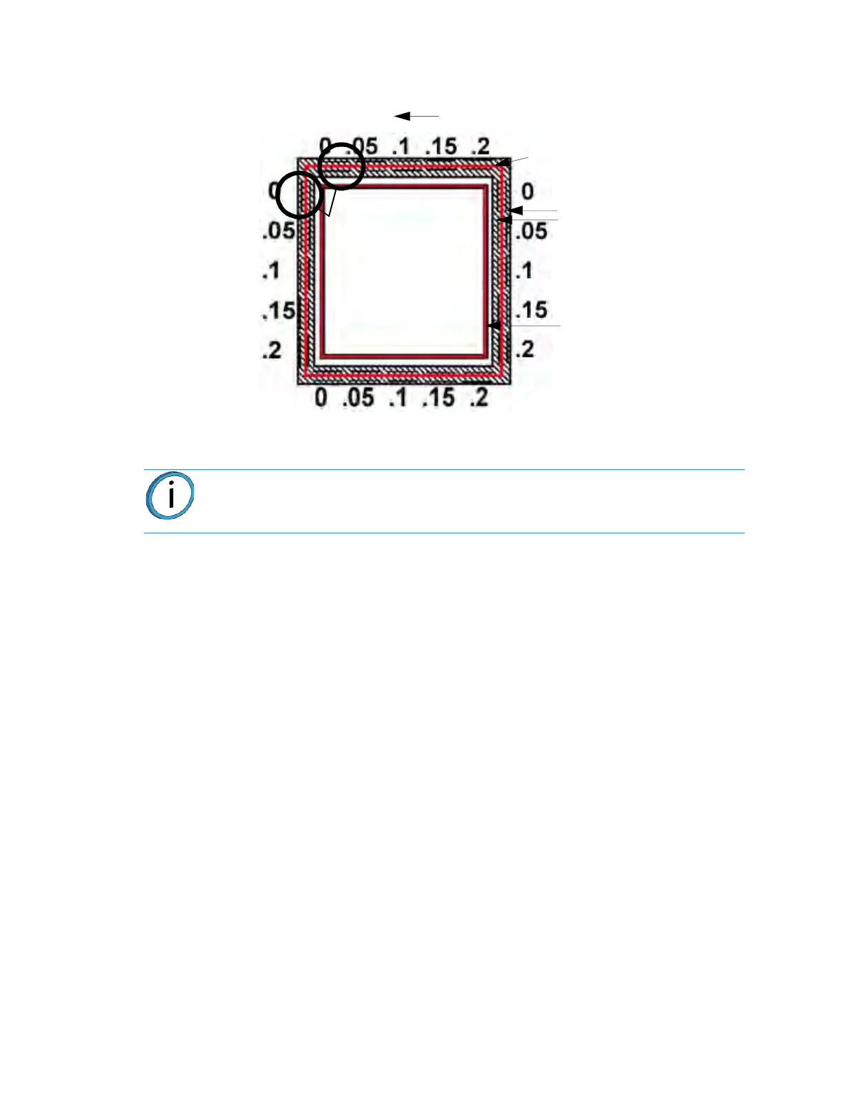
Figure 5-5: Calibration Model - Metric Units
4. Determine the Z Adjustment.
A
. Peel the Support layer from the Z Calibration box.
B
. Measure the thickness of the Support layer with a caliper or micrometer.
•
If the measured value is within ±0.0005 inch (0.01 mm) of Model Tip slice height,
n
o adjustment is necessary.
• Enter the value that is read from the caliber in the “Support Thickness” field.
C
. If an adjustment entry is required, re-run the calibration model on a clean
b
uild sheet.
D. Continue to check for Z Calibration until the Support layer matches the Model
T
ip slice height ±0.0005 inch (0.01 mm).
ADJUST XYZ CALIBRATION OFFSETS FOR CONTROLLER
SOFTWARE VERSION 3.31 AND LATER
Software controller version 3.31 and later creates a calibration box where each axis has its own
line containing both plus and minus values. This eliminates any confusion caused by the
calibration box having two identical axis lines.
The calibration process is performed as it was previously performed. The calibration box is
re
moved from the machine and a magnifying glass is used to verify where the support toolpath is
centered on each axis. Each marker is equivalent to .002 (.05mm). The GUI is used to align the
arrow indicators as they appear on the calibration box. If the support toolpath is centered on the
X or Y markers, the tips are properly calibrated. The Z toolpath is measured the same as the
other calibration jobs.
Note: Do not measure for Z adjustment until the Calibration Model shows the XY
Offset to be less than 0.002 inch (0.05 mm) for the X and Y axis.
Tip Offset Adjustment Indicators
X - Y Support
Calibration Toolpath
X - Y Alignment
Indicators
Z Calibration Box
- Y
+ Y
+ X
Example: Best
Centered Position
This example requires
an adjustment to
Y of -.05 mm. The X axis
requires no adjustment.
- X