139
ELECTRICAL PANEL
The electrical panel is located in the back of the system and accessed from behind two hinged access panels.
These can be either opened or removed by a service representative when they are servicing the system.
Virtually all system communication, interface and control takes place or originates from within electrical panel of
the F900 system. The electrical panel is not intended for customer/user access because potentially deadly
electrical power sources are present. Safe electrical practices must be followed when performing service within
this enclosure. See
“Removing Electrical Power” on page 5 for details on turning off power to the system.
Electrical panel components include the following:
• Motor Amplifiers
•
120V DC Power Supply (3X)
•
Computer
•
AC Filters
•
24V DC Power Supply
•
AC Distribution Bus
•
UPS
•
Oven Thermal Breaker
•
Heater Solid State Relay
Fi
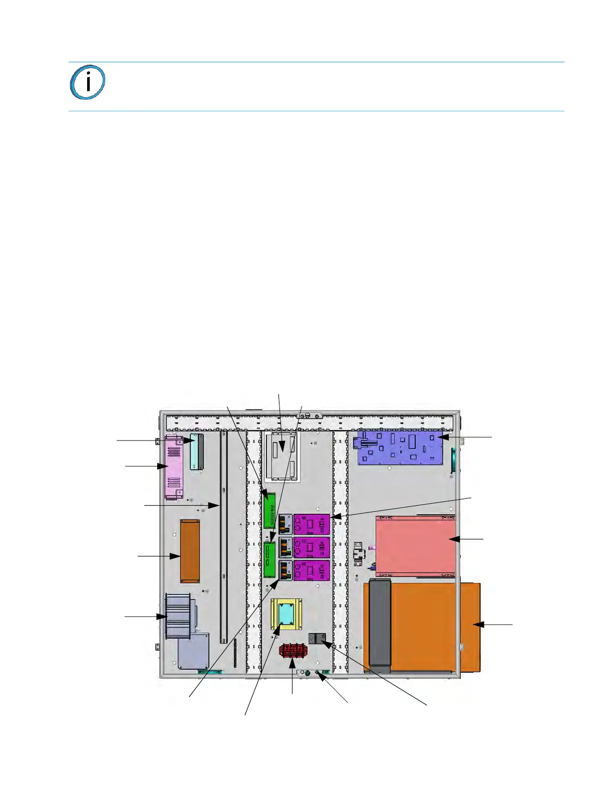
gure 8-1: El
ectrical Panel Component Locations
Note: The following description and diagrams represent the Gen II and Gen III versions only,
serial numbers > 1030
Power Supply
(24V, 250W)
Amp, Programmed X
Amp, Programmed Y
CCA, MAC
Amp, Programmed Z
Din Rail Assy.
Filter, Motor EMI
Filter, AC Line
Line Reactor
SSR, Oven
Power
Heaters
Board
CCA, Auxiliary
120VDC P.S.
CCA Differential
Line Filter
SOK SATA
Computer Assy.
UPS
Breaker, Thermal
Oven
Supply
LED
Block,
Heater
Terminal