8
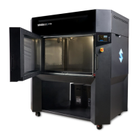
TOP SLIDE COVERS
Allows access to the head, gantry area, and access for changing model and support tips on the head. The
cooling fans are located in this area to provide airflow though the upper portion of the system.
OVEN DOOR
Allows access to the platen, tip wipe assemblies, purge bucket, and completed parts.
CANISTER BAY DOOR
Allows access to the four canister bays, canister levers, and canister LEDs.
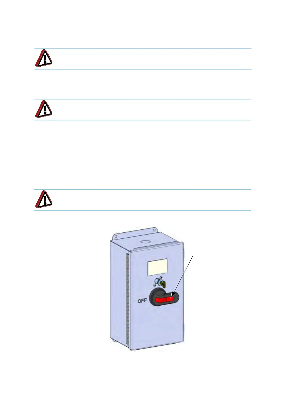
POWER IN DISCONNECT SWITCH
The Power In Disconnect switch, located at the back of the system, acts as the main circuit breaker. Rotating
this switch to OFF will remove AC power to the system. There is a Lockout Bar that can be used to lock the
switch in the off position.
Figure 2-2: Po
wer In Disconnect Switch
Warning: Only use an OSHA or CE approved step stool when accessing the
area under the top slide covers.
Warning: Always wear safety gloves and long sleeves when working in the oven,
with the head, or liquefier tips. these components are very hot.
Warning: High voltage is present in the system when powered off and unplugged
because of the Uninterruptible Power supply (UPS).
Lockout Bar