109
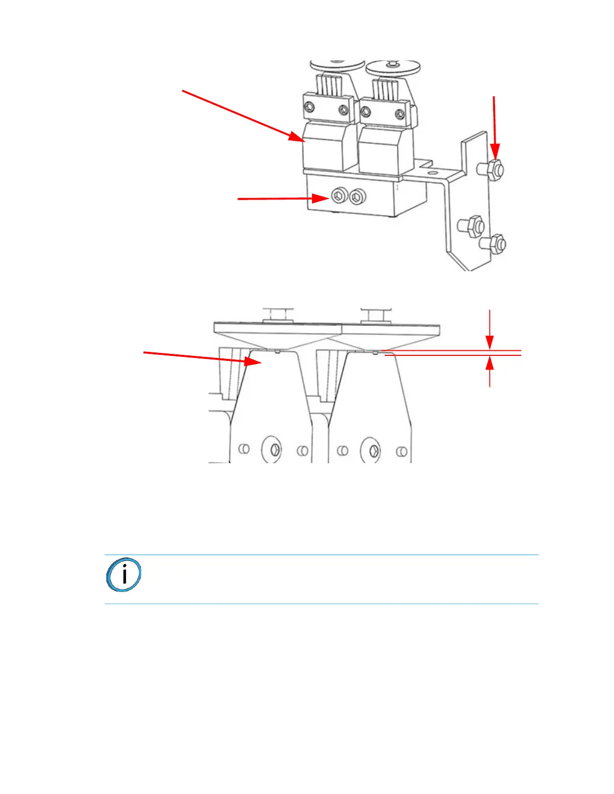
Figure 5-10: Flicker Distance
1. Install the purge bucket.
2
. Perform material load operations for either model or support material. Verify that
t
ip wipe operations are properly cleaning the tip with no material being ejected in
the build area.
3. Build a part and confirm wipe performance.
T16A TIP WIPE ADJUSTMENT
The new T16A requires a different tip to tip wipe height setup then regular tips. Failure to adjust
the tip wipe properly will result in poor part quality. The new T16A does not have a nib and should
not make contact with the flicker but should be just above the flicker.
Note: The flicker of the flicker brush assembly should not rub against the lower
surface of the tip shield during a wipe operation.
Tip Wipe Block (2x)
Adjustment 9/64 Allen screws.
- counterclockwise will raise flicker/brush
- clockwise will lower flicker/brush
Locknuts
(3x)
Flicker
0.020 in.
(0.508 mm)
 Loading...