Introduction
6 Tour of the Syspine Phone System
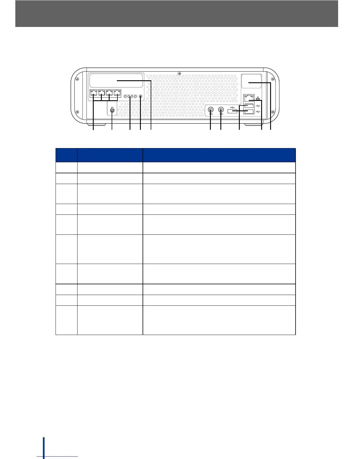
1.3.3 Rear View
No. Item Description
1. Telephone Lines Module 1 telephone lines P1 to P4
2. DC IN Jack Connect the DC power adapter to this jack
3. Phone Line LCDs Indicates phone line activity on the corre-
sponding line
4. Status LED Indicates module 1 connection status
5. Optional
Telephone Lines
Module 2 telephone lines P5 to P8
(optional)
6. LINE OUT Connect an output device, such as a Public
Address system or speaker. See Using a
Public Address System on page 60
7. LINE IN Standard Line-in jack. See Service Manual
for updated functions
8. USB Ports Connect USB devices to these ports
9. LAN Port Connect an Ethernet RJ-45 to the LAN
10. Optional WAN
Port
Connect an Ethernet RJ-45 to the wide area
network (WAN) if the optional Security
Gateway module is installed