EasyManuals Logo

TESTO Saveris User Manual

TESTO Saveris
222 pages
To Next Page IconTo Next Page
To Previous Page IconTo Previous Page
Page #35 background imageLoading...
Page #35 background image
4 Product description
35
Pos: 44 /TD/Produk tbeschreibung/ Übersicht/testo Saver is/04 Converter/ 01 Converter @ 1\mod_119755708 6312_79.docx @ 6416 @ 2 @ 1
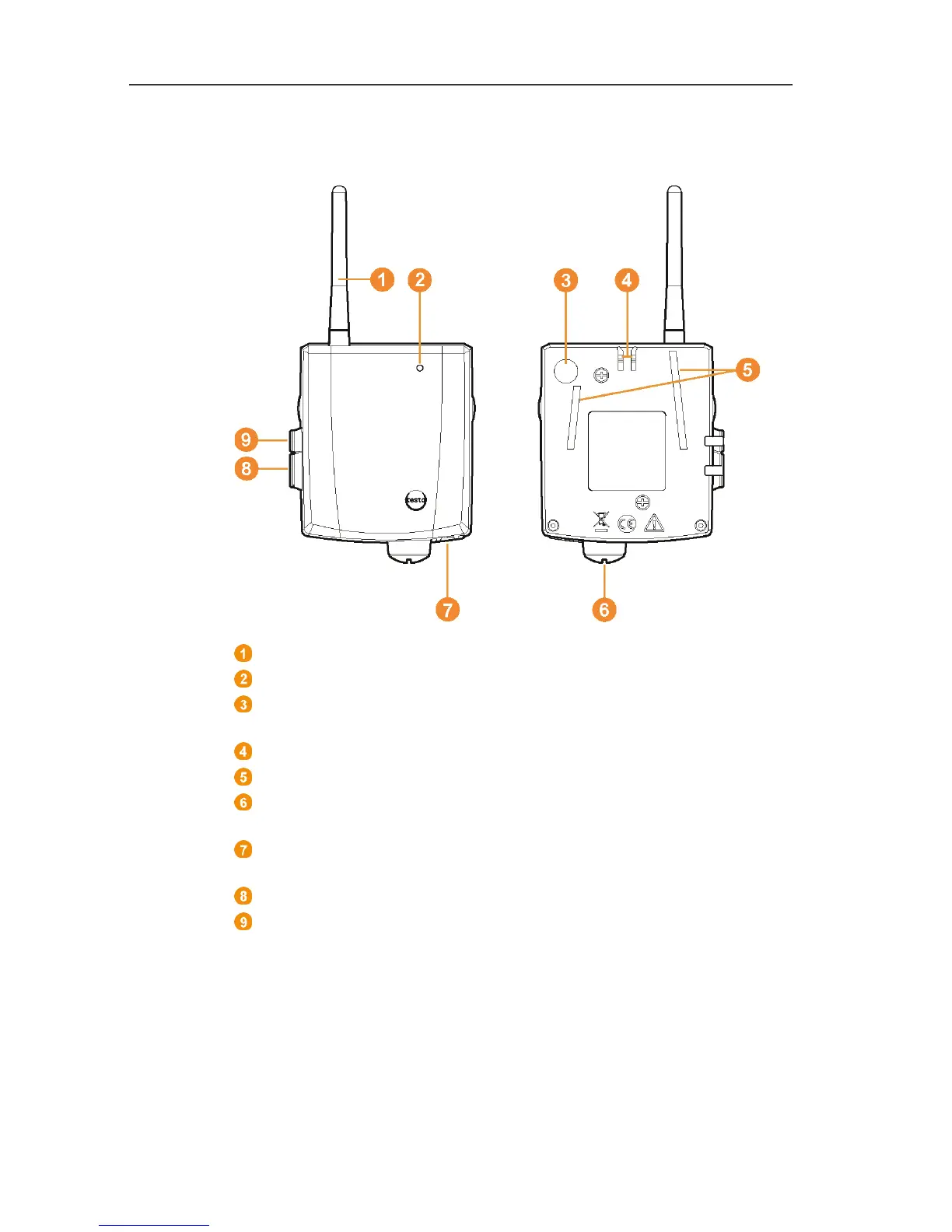
4.7. Saveris converter
Antenna for receiving the measurement data.
LED for status display.
Connect button for connecting the converter to the Saveris base
and for a status request during operation.
Catch for the wall bracket.
Guide rails for the wall bracket.
Input for external 24 V AC/DC power supply.
M1.6 x 1.5 cable coupling
Input for connecting the network cable (optional power supply
via PoE).
Input for service interface.
Input for power supply via mains unit.

Table of Contents

Other manuals for TESTO Saveris

Questions and Answers:

Question and Answer IconNeed help?

Do you have a question about the TESTO Saveris and is the answer not in the manual?

TESTO Saveris Specifications

General IconGeneral
Humidity Range0 to 100 %RH
Measurement ParametersTemperature, Humidity
Data TransmissionWireless
Alarm FunctionYes
Resolution0.1 °C, 0.1 %RH
Radio Frequency868 MHz, 915 MHz
Data StorageInternal memory, Cloud
Power SupplyBattery

Related product manuals