5 First steps
73
Connecting probe or router to converter
1. Briefly press the connect button on the rear of the converter.
- The LED at the converter lights green and the converter is
ready for probe detection.
2. Press the connect key on the rear of the probe/router until the
LED at the probe/router begins to flash orange.
- The LED at the probe/router briefly turns green if this was
detected by the Saveris converter.
The probe/router is connected at the converter and this
transmits the measurement data to the Saveris base.
Pos: 80 /TD/Erst e Schritte/testo Saver is/Hardware erwei tern/03 Ethernet-Fühler einbinden/00 Etherne t-Fühler einsetzen @ 1\ mod_1197552336953_79. docx @ 6336 @ 3 @ 1
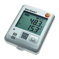
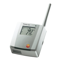
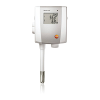
5.14.4. Integrating Saveris Ethernet probe (optional)
In addition to the Saveris radio probes, you can use probes that are
connected to the Ethernet interface of the Saveris base. This also
enables the data transfer from the probe to the base over long
stretches if you do not wish to use a router or converter.
All Ethernet components (Ethernet probe, converter, extender,
base where applicable) must be assigned IP addresses through the
programming adapter (0440 6723) via the Ethernet wizard.
If your computer has the Dynamic Host Configuration
Protocol (DHCP), the Ethernet components
automatically retrieve the IP address. Because the
DHCP address changes as standard following a certain
period of time, the base should be assigned a fixed IP
address. The IP address of the base must be manually
assigned to the probes, extenders and converters
through the adapter.
This chapter contains all required information for this.
You can connect several Ethernet probes to the Saveris
base using a so-called switch. In this context, note that
a maximum of 150 probes can be connected or 450
measurement channels recorded at the Saveris base.
Pos: 81 /TD/Erst e Schritte/testo Saver is/Hardware erwei tern/03 Ethernet-Fühler einbinden/01 Netz werkkabel @ 1\mod_1203421433 000_79.docx @ 8193 @ 4 @ 1