4 Product description
37
Pos: 46 /TD/Produk tbeschreibung/ Übersicht/testo Saver is/05 Analogkoppler /01 Analogkoppler @ 4\ mod_1245762445743_79. docx @ 45338 @ 2 @ 1
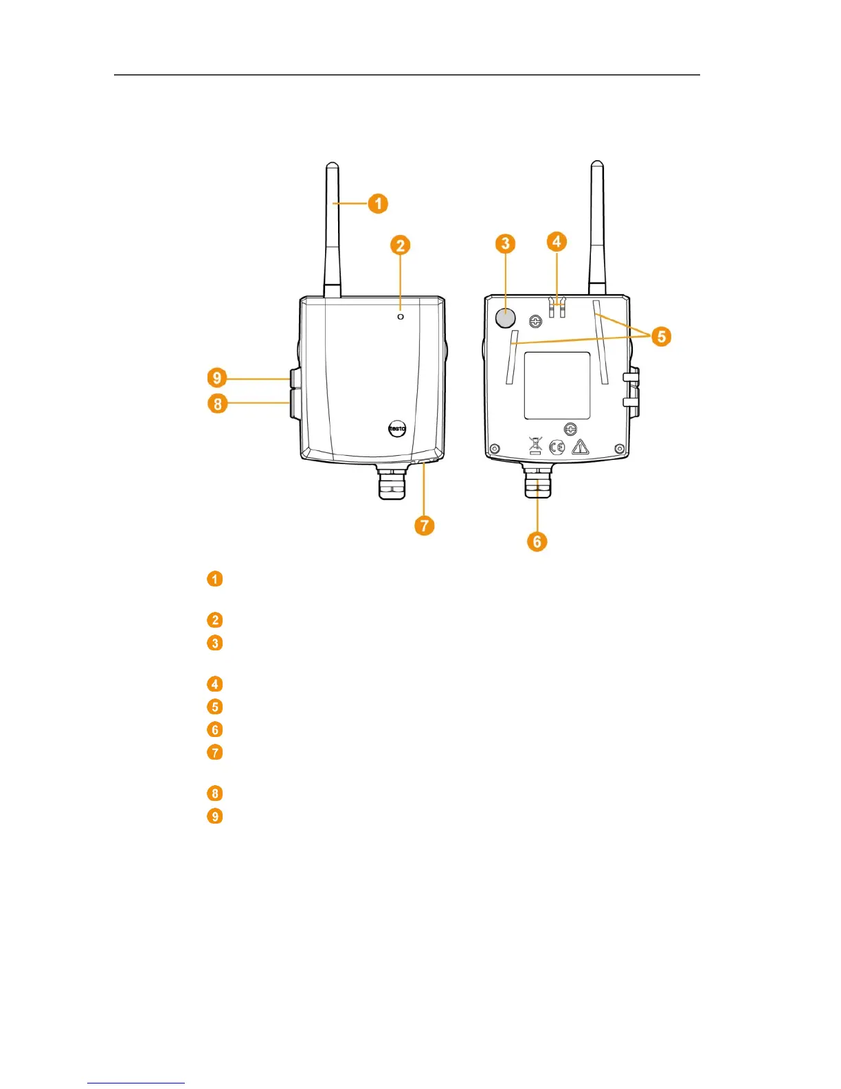
4.9. Saveris analog coupler
Only with radio analog coupler U1: Antenna for sending the
measurement data.
LED for status display.
Connect button for connecting the analog coupler to the Saveris
base and for a status request during operation.
Catch for the wall bracket.
Guide rails for the wall bracket.
Cable coupling M16 x 1.5 for connecting to the transmitter.
Only with Ethernet analog coupler U1E: Input for connecting the
network cable.
Input for service interface.
Input for power supply via mains unit.
Pos: 47 /TD/Produk tbeschreibung/ Grundlegende Eigenschaf ten/testo Saveris P ROF/01 Netzwerkumgebun g @ 1\mod_1198065502375_7 9.docx @ 6744 @ 2 @ 1
4.10. Network environment
The testo Saveris software is installed as a client-server
installation. In the process, the database and the Saveris
Professional Client are installed on a server computer, and
furthermore the Client and Viewer program components can be
installed on additional client computers.
Pos: 48 /TD/--- Seitenwechsel --- @ 0\mod_1173 774430601_0.doc x @ 283 @ @ 1