Installation Premier Elite Series Installation Manual
16 INS176-15
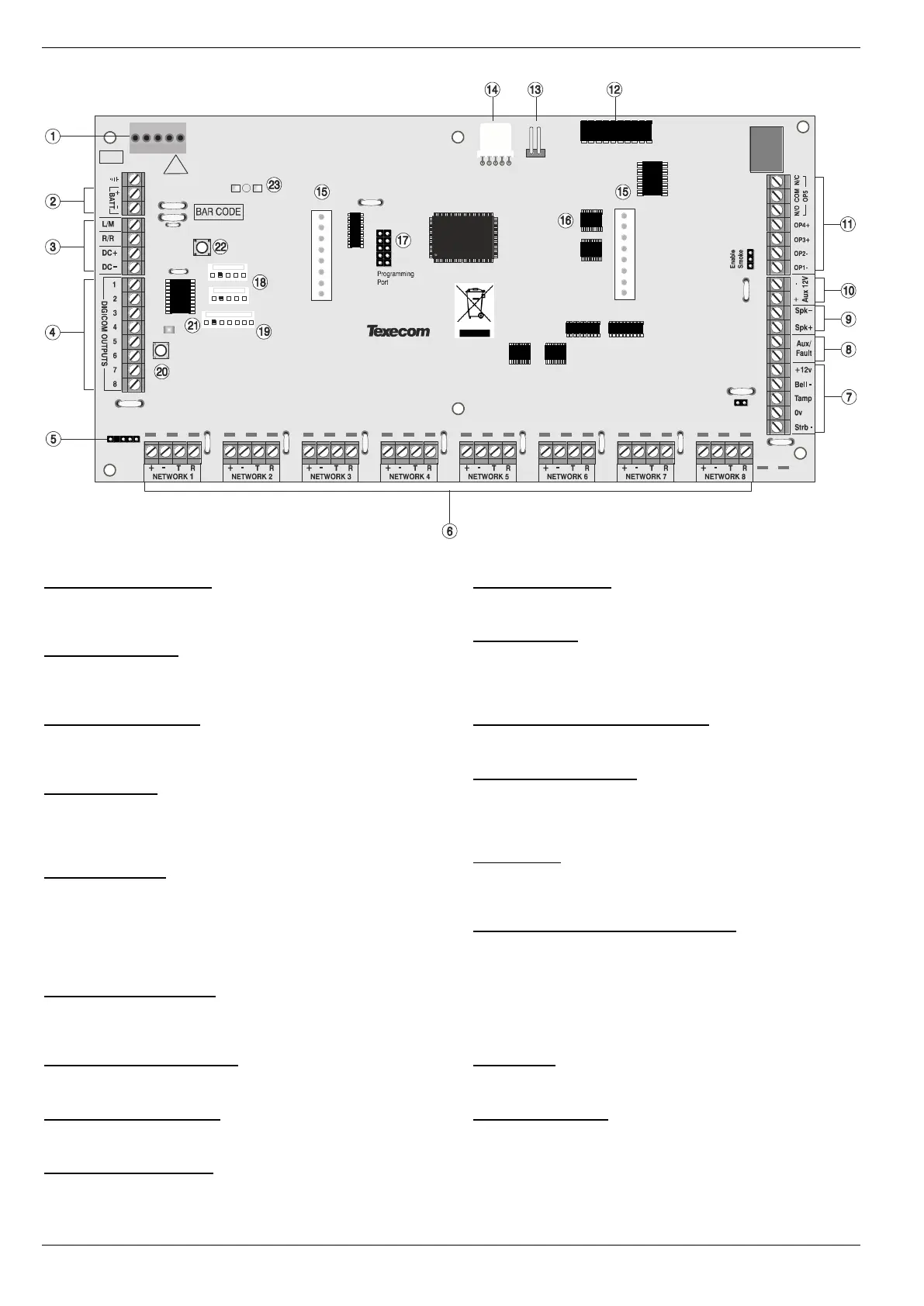
Premier Elite 640 PCB Layout
1: Texecom PSU Connection
Connected to the Texecom Switch Mode Power Supply.
DO NOT CONNECT THE MAINS SUPPLY TO THE AC INPUT
TERMINALS ON THE PCB.
2: Battery Connections
A 12V rechargeable battery must be connected to these terminals in
order to provide continuous system operation in the event of an AC
Mains failure (see page 19 for details).
3: Digicom Power & Inputs
These terminals provide unfused power; remote reset and line fault inputs
and are normally used for connecting a stand-alone communicator to the
control panel (see page 35 for details).
4: Digicom Outputs
Outputs 1 to 8 are low current (100mA ‘-ve’ applied) and would
normally be used when connecting a stand-alone communicator to
the control panel (see page 35 for details). Each output is fully
programmable (see page 84 for details).
5: Engineers Keypad
A portable Engineers keypad can be plugged on here to allow easier
access for programming and testing.
When using a keypad as an Engineers keypad, the address
must be set to ‘10’ (see page 23 for details). The keypad zones
and lid tamper are not monitored.
6: Network Data Connections
Networks 1 - 8 provide connection for the keypads and zone
expanders. The ‘+’ and ‘–’ terminals provide power whilst the ‘T’
transmits data and ‘R’ receives data (see page 20 for details).
7: External Sounder Connections
These terminals are used for connecting to an external sounder unit
(see page 34 for details).
8: Auxiliary/Fault Connections
These terminals can be used for monitoring the tamper loop of an
auxiliary device (see page 34 for details).
9: Loudspeaker Connections
These terminals can be used for connecting up to one 16Ω or two 8Ω
loudspeakers (see page 34 for details).
10: Auxiliary 12V Power
These terminals are for connecting devices that require 12V power
(protected by a 1A fuse).
11: Panel Outputs
Outputs 1 & 2 are 500mA ‘-ve’ applied, outputs 3 & 4 are 500mA
‘+ve’ applied and output 5 is a clean contact relay (see page 35 for
wiring details). These outputs are all fully programmable (see page
83 for details).
12: Plug-on Communicator Connections
This socket provides connection for the plug-on communicator (see
page 37 for details).
13: Box Tamper Connection
The box tamper micro switch is connected here. The micro switch
provides tamper protection for the main control panel in case of
unauthorised access. To disable the box tamper, remove the micro
switch lead and fit a jumper link across the two pins.
14: Com Port 3
Com Port 3 is a serial communications port and can be used for
connecting a PC running Wintex or any supported serial device to the
control panel (see page 101 for details).
15: Plug-on RedCARE/Dualcom Connections
These pins provide connections for a plug-on RedCARE, Dualcom,
Digicom or RM8 Relay module. Each output is fully programmable
(see page 84 for details).
When a device is plugged on to these pins, not all outputs may
be available, please refer to the relevant documentation for
details.
16: NVM 1 & 2
All system programming data and the event log is stored in one or
two non-volatile memory devices.
17: Flash Upgrade Port
For use with the Flasher interface to update panel firmware.

 Loading...