Premier Elite Series Installation Manual Installation
INS176-15 15
18: Communication Ports
Com Port 1 is a serial communications port and can be used for
connecting a PC running Wintex or any supported serial device to the
control panel (see page 101 for details).
Com Port 2 is a serial communications port and can be used for
connecting a PC running Wintex or any supported serial device to the
control panel (see page 101 for details).
19: Network Data Indicators
The red LED indicates that data is flowing out of the control panel
and normally flashes very quickly. The green LED indicates that data
is flowing into the control panel and normally flashes slowly, the
green LED flashes faster as more devices are connected (see page
21 for details).
For a complete list of factory defaults, see the Quick
Reference Guide supplied with your panel.
20: Load Defaults Button
Press and hold this button whilst applying power to the control panel
to load the factory default settings. Press and hold this button for 7
seconds with power already on the panel to restore just the Engineer
code to the factory setting of
1234
. See page 53
for full details.
Loading the factory defaults can take up to 30 seconds to
complete.
Loading defaults will only be possible if the NVM has not been
locked (see page 71 for details).
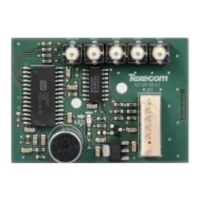
21: Expansion
The Expansion Port can be used for connecting a 60XiD Zone
Expander (see page 33 for details) or an AV Module (see page 42 for
details), X-10 Module (Obsolete), Speech Module or a Memory
Module.
22: Heartbeat LED/Power Light
Flashes steadily to indicate that the control panel is functioning
correctly. If the light is ON or OFF all the time, then there could be a
problem (see page 48 for details).
23: Current Reading Pads
To calculate the current draw of the control panel, measure the
voltage across the two pads and multiply by 10 i.e. Reading = 34mV
(x10) = 340mV = 340mA.
24: NVM 1 & 2
All system programming data and the event log is stored in one or
two non-volatile memory devices.
F1 - F5: Protection Fuses (48, 88 and 168)
The following fuses are provided:
• F1 (1Amp) Auxiliary 12V Power fuse
• F2 (1.6 Amp) Battery fuse (electronic PTC)
• F3 (1 Amp) Network 1 fuse
• F4 (1 Amp) Bell/Strobe fuse
• F5 (1 Amp) Network 2 fuse (168 only)

 Loading...

