13-12
dummyheaddummyhead
ENGINE REMOVAL/INSTALLATION
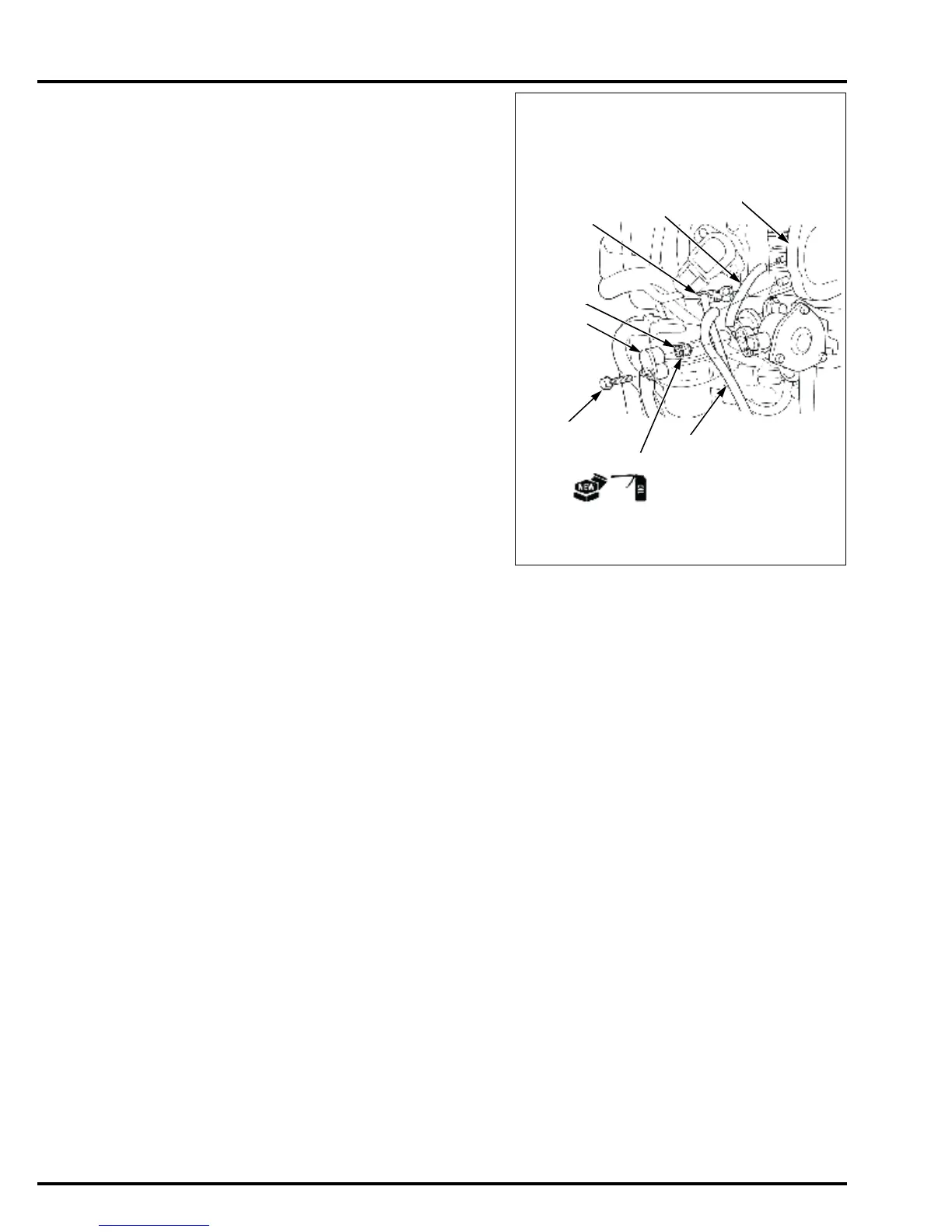
Connect the pressure regulator control tube [1] to the
intake manifold [2] and set the tube in tube clamp D [3].
Connect the vinyl tube [4] to the intake manifold.
Apply engine oil to new O-rings [5] and install them on
the fuel pipe joint [6].
Insert the fuel pipe joint on the vapor separator by
pushing it until it stops.
Connect the fuel hose [7] to the vapor separator.
• Connect the fuel hose securely until the connecting
surface of the fuel hose comes in contact with the
connecting surface of the vapor separator.
Install and tighten the bolt [8].
Install the following
– Gear case/extension separator (XRT type only)
(page 16-7)
– Seal holder (page 19-12)
– Shift link bracket/neutral switch (page 19-11)
– Starter cable/fuse cable (page 10-8)
– Under cover rear bracket (page 6-16)
– Under cover front bracket (page 6-14)
– L./R. engine under cover (page 6-7)
– Engine cover
– Battery negative (-) cable
To start the engine after installation, follow the starting
procedure after assembly (page 12-4).


 To Next Page