19-43
dummyheaddummyhead
CONTROLS
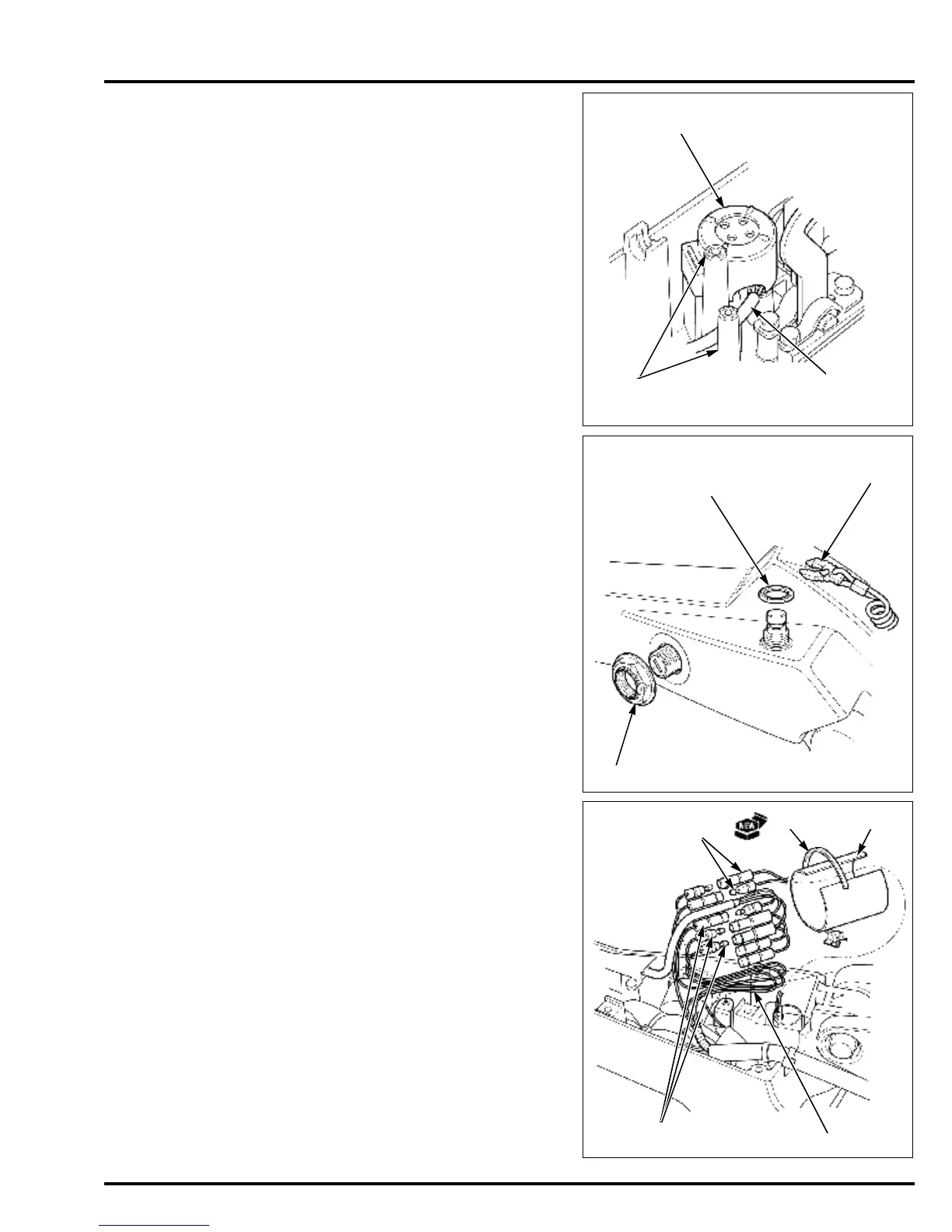
Install the warning buzzer [1] in the housing.
Route the warning buzzer wire [2] between the
projections [3] in the housing as shown.
• Operate the throttle arm and check that it does not
interfere with the warning buzzer wire.
Install the nut [1] on the combination switch and tighten
the nut to the specified torque.
Install the nut (16 mm) [2] on the emergency stop
switch and tighten the nut to the specified torque.
Set the switch clip [3] to the emergency stop switch.
Connect the power trim/tilt switch connectors [1]
(except LHGX type).
Connect the emergency stop switch connectors [2].
Fold back the power trim/tilt switch wire [3] and set it in
tube B [4] as shown (Except LHGX type).
Holding the emergency stop switch connectors in tube
B, clamp tube B at the connectors securely using a new
harness band clip [5].
After clamping with the harness band clip, cut off the
excess band at 15 – 20 mm (0.6 – 0.8 in) from the
fastener end.
• Check that the wires are not interfering with the tiller
handle.
TORQUE: 3.9 N·m (0.40 kgf·m, 2.9 lbf·ft)
TORQUE: 1.2 N·m (0.12 kgf·m, 0.9 lbf·ft)



 To Next Page