32
PREPARATIONS
CONNECTING EXTERNAL I/O TERMINALS
DATA OUTPUT
This instrument can be connected to a personal computer and external printer etc. via the
RS232C or USB terminals.
1 Connect one end of the RS232C cable to the RS232C OUT terminal on the instrument.
2 Connect the other end of the RS232C cable to the PC and other external device.
DATA INPUT
This instrument is provided with a USB IN terminal. In addition, it supports the patient ID input
using a data bar code reader.
LAN OUTPUT
This instrument can be connected to a PC on local area network (IMAGEnet etc.) via the LAN
OUT terminal.
1 Connect the Ethernet cable to the LAN I/O terminal of this instrument.
2 Connect the other end of the Ethernet cable end to the external device.
CAUTION
To avoid electric shock, do not touch the external connection
terminal and the patient at the same time.
Use the external device complying with IEC60950/IEC60950-1, UL60950/
UL60950-1 or UL60601-1.
The USB I/O terminal (USB A) is used to connect a keyboard, mouse and color
printer. The USB OUT terminal (USB B) is used to connect an external PC, etc.
When connecting a USB cable, be sure to use the cable with correct shape of plug.
For external printer inquiries, call your dealer or TOPCON at the address printed
on the back cover of this manual.
As for the data bar code reader available with this instrument, please contact with
your TOPCON dealer or your local TOPCON office listed on the back of this man
-
ual.
For inquiries about the LAN connectivity, call your dealer or TOPCON at the
address printed on the back cover of this manual.
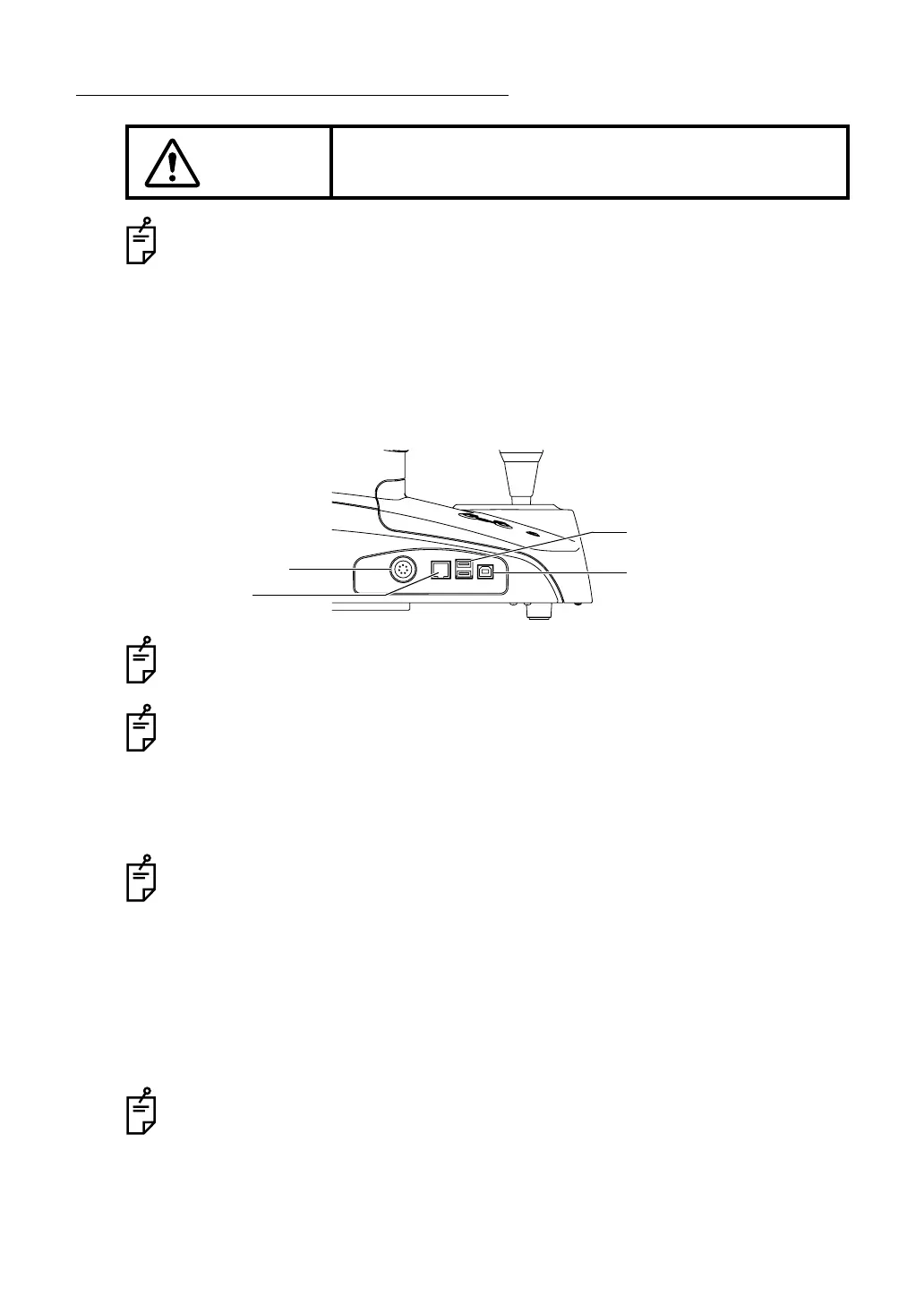
USB OUT terminal (USB B)
RS232C OUT terminal
LAN I/O terminal
USB I/O terminal (USB A)