97
DISPLAYING THE MEASUREMENT RESULT
Near the "Map Setting" displayed on the right, the following display setting can be done:
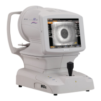
• Hartmann detection point overlay (Hartmann image)
When turned on, Hartmann detection point is displayed with a yellow cross scale.
• Hartmann detection grid overlay (Hartmann image)
When turned on, Hartmann detection grid is displayed with a white square.
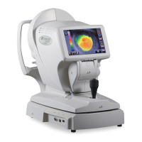
• Placido ring detection overlay (Mire image)
When turned on, the detected Placido ring is displayed.
• Pupil detection overlay (Mire image)
When turned on, the detected pupil is displayed with a yellow circle.
• Angle Scale Overlay (Corneal Mire image)
When turned to ON, an angle scale is displayed.
ANALYSIS SETTING MENU
Settings can be changed from the SETTINGS screen.
SETTING TOPOMAP SCALE TYPE
• The map scale can be changed in the SETTINGS menu. See "SETTING THE TOPOMAP
SCALE TYPE (TOPOMAP SCALE - TYPE)" on page 149.
SETTING ABERRATION MAPS
• The overlay object can be changed in the SETTINGS menu (cross scale, angle scale, mm
grid scale). See "
SETTING THE TOTAL ABERRATION MAP OVERLAY - CROSS SCALE"
on page 147.
SETTING SIMULATION
Settings can be changed from the SETTINGS screen.
• Eyesight value can be changed.
See "SETTING OPTOTYPE SIMULATION 1 (UPPER)" on page 151.
• For the chart, the direction can be changed to top, bottom, left and right.
See "SETTING OPTOTYPE DIRECTION" on page 152.
• Brightness may be normalized. In the initial state, it is not normalized. When normalized,
Landolt's ring is contrasted and the direction of blur is made more clearly visible. It is
assumed that, when not normalized, the image is less contrasted by blur and seen nearer.
See "SETTING THE NORMALIZATION OF BRIGHTNESS OF SIMULATION (NORMALIZE
DESTINY OF SIMULATIONS)" on page 152.
Items set by "Map Setting," displayed on the right side of the enlargement display,
can also be set by the items of "DISPLAY" of the "SETTINGS screen." See "
DIS-
PLAY SETTING (DISPLAY)" on page 142.