16
COMPONENTS
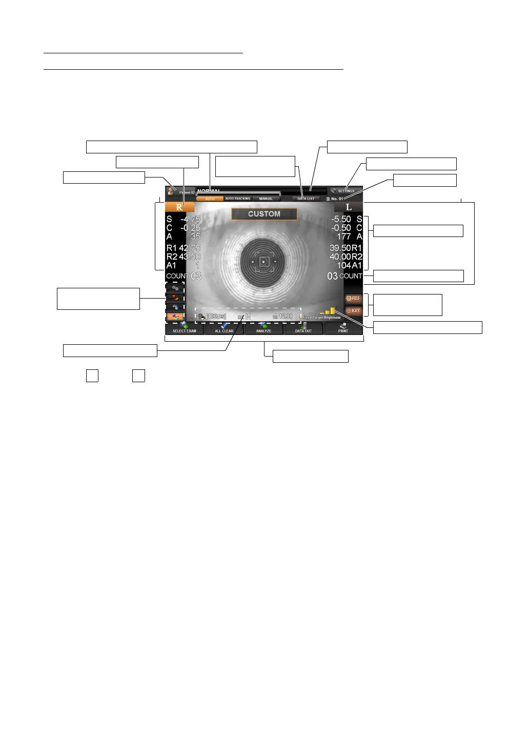
CONTROL PANEL COMPONENTS
(MEASUREMENT SCREEN IN THE REF/KRT MODE)
AUTO MEASUREMENT SCREEN
The control panel displays observation images and shows set conditions and measure-
ment results. The control panel is also used as a touch panel for performing various oper-
ations and settings.
(1) button, button Select the right/left eye. When the button is tapped, the main body
moves in the selected direction. (see page 52)
The selected R/L button is displayed in orange. (see page 52)
Continuous measurements of right and left eyes and the mea-
surement of only the right/left eye can be set.
(2) Machine No. The machine No. is displayed. This can also be hidden (see page
135).
(3) Patient ID The Patient ID INPUT screen is displayed. The patient ID is dis-
played on the right.
(4) Measurement value Measurement values of REF (S, C, A) and KRT (R1, R2, A1) are
displayed.
(5) Measurement count The measurement count each of the right/left eye is displayed.
*(4)-(5) are displayed on the right/left ends of the screen.
(6) Display of set values Displaying the current setting values including the Hartmann
exposure time, astigmatism sign and vertex distance. The
Hartmann Exposure time can be changed on this screen. (see
page
51)
(7) Function button A list of operable functions is displayed. Select the relevant button
on the touch panel. (see page
17)
(8) AUTO button/AUTO TRACKING button/MANUAL button
Measurement mode is changed for AUTO, AUTO TRACKING
and MANUAL. (see page
50)
(9) Measurement Data List button
Measurement values are displayed in list form. (see page 70)
(7) Function button
Right eye
Left eye
(4) Measurement value
(5) Measurement count
(2) Machine No.
(8) AUTO/AUTO TRACKING/MANUAL button
(6) Display of set values
(10) Fixed Target Brightness
(11) REF button,
KRT button
(3) Patient ID button
(1) R button, L button
(9) Measurement
Data List button
Display of patient ID
(12) SETTINGS button
(13) Exam purpose
shortcut button