InstallingtheMixingBoxAssembly
g036620
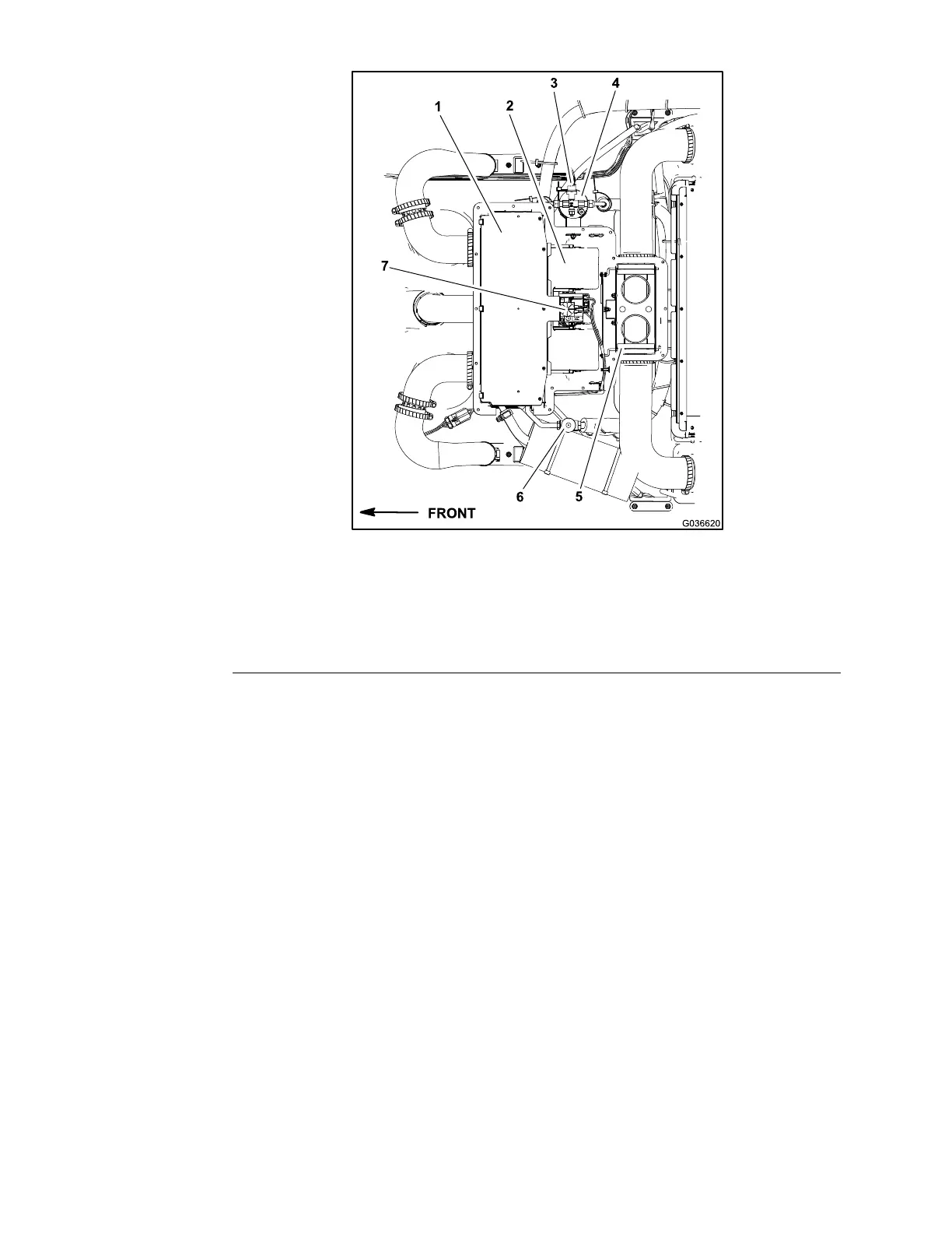
Figure330
1.Evaporatorandheatercore5.Airdiverterassembly
2.Blowerfan
6.Airconditioningexpansionvalve
3.Airconditioningbinaryswitch
7.Airconditioningfreezeswitch
4.Airconditioningdrier-receiver
1.Installallthemixingboxcomponentsthatwereremoved(Figure329and
Figure330).
Note:Ensurethattheexpansionvalveiscoveredwithinsulatingtapeto
preventcondensationissues.
2.Ensurethatthecondensationhosesaresecuredtothedrainttingsonthe
bottomofthemixingboxassembly.Also,routethehosestothecabframe
forproperdrainingofthecondensate.
3.Ensuretoconnecttheelectricalconnectorsfromthemixingboxwireharness
andbinaryswitchontheairconditioningdrier-receiver.
4.Ifanyairconditioningsystemcomponentswereremovedfromthecab
headliner,ensurethatallthemachineairconditioningcomponentsare
installedandsecure.
5.Haveacertiedairconditioningservicetechnicianevacuatetheair
conditioningsystemcompletely,properlyrechargethesystemwithR134a
refrigerant,andperformtheleaktestonthesystem.
Note:Thecapacityoftheairconditioningsystemis1.55kg(3.43lb)of
R134arefrigerant.
OperatorCab:ServiceandRepairs
Page8–22
Groundsmaster360
16225SLRevC

 Loading...


