Workman HDX Auto Page 7 − 43 Hydraulic System
Removal (Fig. 34)
1. Park vehicle on a level surface, raise and support bed
(if installed), shut engine off and engage the parking
brake. Remove key from the ignition switch.
2. Remove seat base from vehicle (see Seat Base in
the Service and Repairs section of Chapter 7 − Chassis).
3. Read the General Precautions for Removing and
Installing Hydraulic System Components at the begin-
ning of this section.
CAUTION
Before performing any service or repair on hy-
draulic system components, relieve system pres-
sure to avoid injury from pressurized hydraulic
oil. Stop the engine, remove key from the ignition
switch, rotate the steering wheel in both direc-
tions, lower or support the bed and operate other
hydraulic accessories.
4. Label and disconnect hydraulic tubes from lift valve.
Install caps or plugs in tubes to prevent contamination
and leakage of hydraulic oil. Install plugs in valve ports.
5. Remove lift valve from vehicle using Figure 34 as a
guide.
6. If hydraulic fittings are to be removed from lift valve,
mark fitting orientation to allow correct assembly. Re-
move fittings from valve and discard O−rings.
Installation (Fig. 34)
1. If fittings were removed from lift valve, lubricate and
place new O−rings onto fittings. Install fittings into valve
openings using marks made during the removal process
to properly orientate fittings. Tighten fittings (see Hy-
draulic Fitting Installation in the General Information
section of this chapter).
2. Install lift valve to vehicle using Figure 34 as a guide.
3. Replace O−rings on hydraulic lines and fittings. Re-
move caps and plugs from tubes and fittings. Connect
hydraulic tubes to lift valve (see Hydraulic Hose and
Tube Installation in the General Information section of
this chapter).
4. Install seat base to vehicle (see Seat Base in the Ser-
vice and Repairs section of Chapter 7 − Chassis). Make
sure that lift lever can be moved in control plate slot to
allow correct operation of lift lock.
5. Check oil level in hydraulic reservoir. Add hydraulic
oil to reservoir if necessary.
6. Start the engine, operate at idle speed and operate
the lift lever in both directions until air is out of hydraulic
system.
7. Stop the engine and recheck oil level in hydraulic
reservoir. Add hydraulic oil to reservoir if necessary.
8. On TC models, verify correct operation of lift lever in-
terlock switch.
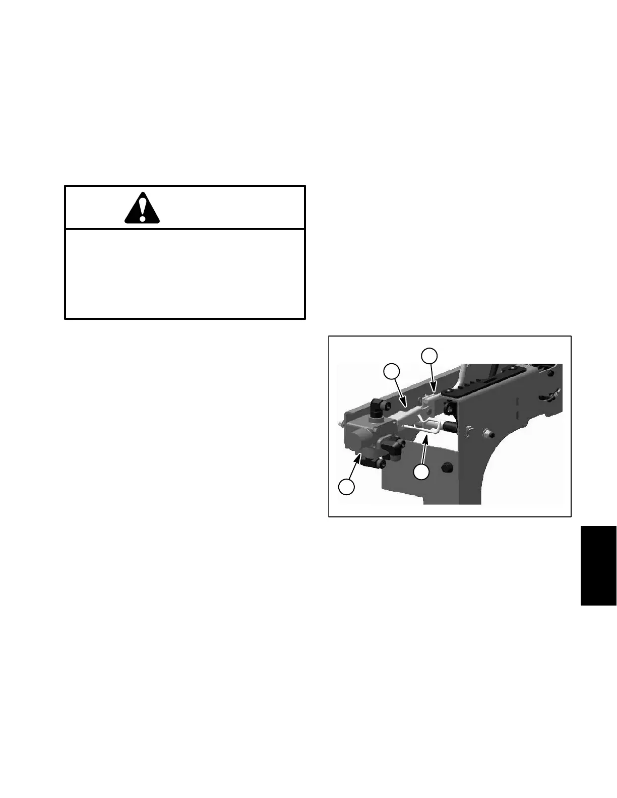
1. Lift lever
2. Link
3. Retainer pin
4. Lift valve
Figure 35
2
1
4
3
Hydraulic
System