Workman HDX AutoPage 4 − 44Drive Train
Rear Differential Service
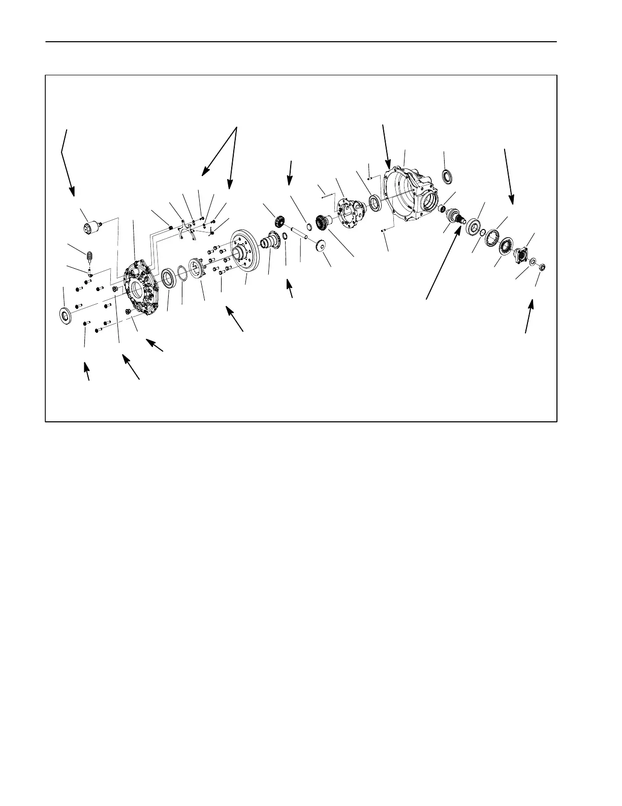
Figure 48
1. Fill plug
2. Engagement dog
3. Drain plug
4. Torx screw (2)
5. Flange head screw (8)
6. Vent tube
7. Hex nut
8. Lock washer set (2 halves)
9. Dowel pin (2)
10. Pinion gear
11. Shim
12. Lock collar
13. Ball bearing
14. Ball bearing
15. Caged needle bearing
16. Torsion return spring
17. Compression spring
18. Output cover
19. Gear case
20. Cap screw (8)
21. Spiral gear
22. Output gear
23. Output gear
24. Expansion plug (2)
25. Dowel pin
26. Differential gear pin
27. Differential pinion gear (2)
28. Differential housing
29. Ball bearing
30. Coupler
31. Fork retainer (2)
32. Shift fork
33. Solenoid
34. Seal
35. Seal
36. O−ring
37. Seal
38. Breather bellows
24
29
30
8
37
14
15
9
21
27
25
6
28
11
13
18
3
5
1
33
17
32
31
4
16
22
23
10
20
12
19
34
35
4
31
9
26
36
7
2
10 to 14 ft−lb
(14 to 19 N−m)
15 to 20 ft−lb
(21 to 27 N−m)
7 to 10 ft−lb
(9.5 to 13.5 N−m)
54 to 59 ft−lb
(74 to 80 N−m)
195 to 215 ft−lb
(265 to 291 N−m
490 to 510 ft−lb
(665 to 691 N−m)
20 ft−lb
(27 N−m)
10 to 14 ft−lb
Loctite #680
Loctite #680
38
(14 to 19 N−m)
24
27
Thread Locker
High Strength (Red)
Retaining Compound
Retaining Compound
Apply
Silicone Sealant
Rear Differential Disassembly (Fig. 48)
1. Clean the outside of the differential assembly.
2. Remove the solenoid (item 33) from the differential
cover. Then, remove compression spring (item 17) from
cover.
3. Support the differential assembly with the output cov-
er side facing up.
4. Remove the eight (8) flange head screws that secure
the output cover (item 18) to the gear case.
IMPORTANT: Do not use a pry bar or screw driver on
the differential output cover and gear case mating
surfaces when separating the cover from the gear
case. Damage to the sealing surfaces of the compo-
nents may result.
5. Using pry point areas as shown in Figure 49, carefully
separate the output cover from the gear case and then
remove the output cover. Locate and retrieve the shim
(item 11) and engagement dog (item 2).
6. For assembly purposes, note location of dowel pins
(item 9) in the cases. Remove pins to prevent them from
falling out unexpectedly.