Workman HDX AutoPage 4 − 18Drive Train
Speed Limiter Assembly
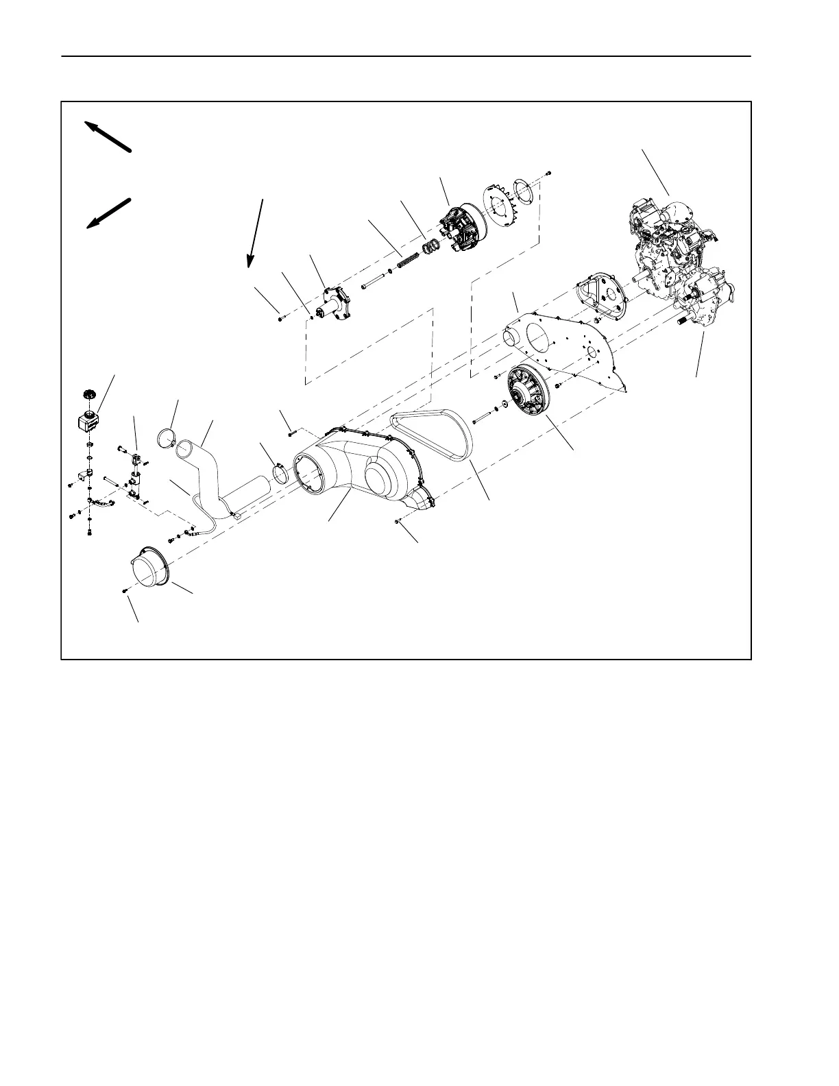
Figure 21
FRONT
RIGHT
1. Engine
2. Transmission
3. Primary clutch
4. Secondary clutch
5. CVT drive belt
6. Washer head screw (3)
7. Speed limiter cover
8. Banjo washer
9. Flange head screw (6)
10. Speed limiter assembly
11. Compression spring
12. Compression spring
13. Speed control hose
14. CVT enclosure cover
15. Washer head screw (9)
16. Washer head screw (2)
17. Spanner plate
18. CVT intake hose
19. Hose clamp (2)
20. Cylinder
21. Reservoir
2
3
6
8
9
10
11
13
1
5
7
12
14
15
16
4
17
18
19
20
105 to 120 in−lb
(11.9 to 13.5 N−m)
19
21
The speed limiter assembly is used on the Workman Au-
to vehicle to adjust the maximum opening of the primary
clutch moveable sheave. The vehicle speed range can
easily be adjusted with the speed range lever to limit the
maximum ground speed for operations that require a
constant speed (e.g. spraying or topdressing). The
speed range lever (Fig. 22) is used to select one of the
four (4) work−speed ranges that are used to limit maxi-
mum ground speed or a transport speed range that is
used when the machine is moved between job sites.
The speed limiter control uses a manually operated hy-
draulic cylinder to change the location of the piston in the
speed limiter cover attached to the primary clutch. The
piston location determines the maximum opening of the
primary clutch.