Workman HDX Auto Page 4 − 17 Drive Train
IMPORTANT: To prevent speed control system con-
tamination, clean components before disassembly.
4. Remove speed control components as needed using
Figures 17, 19 and 20 as guides. If hydraulic hoses are
removed, discard banjo washers and replace during as-
sembly.
NOTE: If speed limiter assembly (item 2 in Fig. 17)
needs to be removed or disassembled, see Speed Lim-
iter Assembly and Speed Limiter Cover Service in this
section.
Assembly (Fig. 17)
1. Install all removed speed control components using
Figures 17, 19 and 20 as guides.
A. If banjo bolts (item 7 in Fig. 20) were removed
from reservoir fitting cylinder, use new banjo washers
(item 6 in Fig. 20) on both sides of hose fitting and
torque banjo bolt from 108 to 132 in−lb (12.3 to 14.9
N−m) during assembly.
2. If hydraulic system was opened during disassembly,
bleed speed control system (see Bleed Speed Control
System in this section).
IMPORTANT: Use DOT 3 brake fluid in the speed
control system.
3. Make sure that fluid level in speed control reservoir
is correct. Add DOT 3 brake fluid to reservoir as needed
to adjust level.
4. Install control plate to seat base and secure with six
(6) washer head screws. Install knobs to speed range
lever and hydraulic lift lever.
Figure 19
1
5
4
3
2
1. Speed range lever
2. Reservoir
3. Cylinder
4. Clevis pin
5. Clevis pin
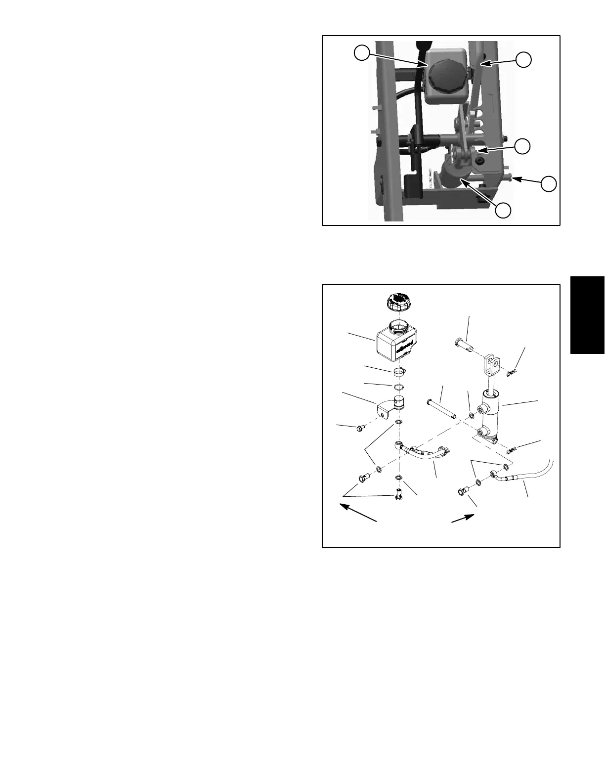
Figure 20
1. Reservoir
2. Worm clamp
3. O−ring
4. Reservoir fitting
5. Washer head screw
6. Banjo washer
7. Banjo bolt
8. Hose
9. Cylinder
10. Clevis pin
11. Hair pin
12. Clevis pin
13. Speed control hose
2
3
6
8
9
10
11
13
1
5
7
12
4
6
6
7
11
6
108 to 132 in−lb
(12.3 to 14.9 N−m)
SafetyProduct Records
Drive Train