Workman HDX Auto
Page 3 − 5
Kohler Gasoline Engine
Service and Repairs
Accelerator Control
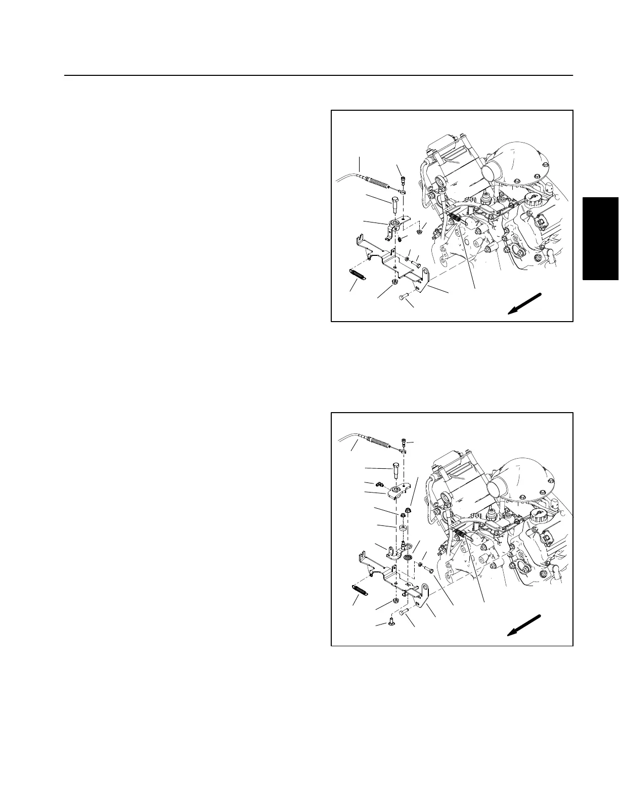
Two styles of accelerator control have been used on
Workman HDX Auto machines. On vehicles with serial
numbers below 315000000 (Fig. 4), the accelerator
control includes a bellcrank that is rotated by the accel-
erator cable to change engine speed. Vehicles with seri-
al numbers above 315000000 (Fig. 5) use an
accelerator control with additional components.
Disassembly (Fig. 4 or 5)
1. Park vehicle on a level surface and engage parking
brake.
2. Raise or remove the cargo bed or other attach-
ment(s). If bed is raised, place safety support on lift cylin-
der.
3. Make sure that the engine is stopped and the key is
removed from ignition switch. Allow engine to cool.
4. Remove accelerator control components as needed
using Figure 4 or 5 as a guide. If engine governor spring
needs to be disconnected from bellcrank, note attach-
ment points for assembly purposes.
Assembly (Fig. 4 or 5)
1. Install removed accelerator control components to
engine using Figure 4 or 5 as a guide.
2. On vehicles with serial numbers above 315000000
(Fig. 5), make sure that ball bearing (item 15 in Fig. 5)
is lightly contacting bellcrank. If necessary, loosen
flange nut (item 5 in Fig. 5) and move throttle lever until
ball bearing is in light contact with bellcrank. Tighten nut
after adjustment.
3. Make sure that the engine governor spring is at the
end of the slot in the bellcrank (item 3 in Fig. 4) or throttle
lever (item 12 in Fig. 5) without being tensioned. If the
governor spring is tensioned, the engine throttle will not
be closed when the accelerator pedal is released.
4. After assembly is completed, make sure that bell-
crank moves freely as accelerator pedal is depressed
fully and released.
5. Lubricate grease fitting on bellcrank.
6. Check adjustment of accelerator control (see Adjust
Accelerator Control in the Adjustments section of this
chapter).
7. Lower or install cargo bed or attachment(s).
1
2
3
4
5
6
7
8
9
10
11
12
12
Figure 4
1. Throttle bracket
2. Cap screw (4)
3. Bellcrank
4. Shoulder screw
5. Flange nut
6. Grease fitting
7. Accelerator cable
8. Shoulder bolt
9. Flange nut
10. Jam nut
11. Cap screw
12. Governor spring
FRONT
SERIAL NUMBER BELOW 315000000
Figure 5
1. Throttle bracket
2. Cap screw (4)
3. Bellcrank
4. Shoulder screw
5. Flange nut (2)
6. Grease fitting
7. Accelerator cable
8. Shoulder bolt
9. Jam nut
10. Cap screw
11. Extension spring
12. Throttle lever
13. Carriage screw
14. Idler bushing
15. Ball bearing
16. Flange nut
17. Governor spring
15
2
3
4
5
6
7
8
9
10
11
12
16
13
14
1
5
FRONT
17
SERIAL NUMBER ABOVE 315000000
Gasoline Engine
Kohler