Workman HDX Auto Page 7 − 59 Hydraulic System
Removal (Fig. 46)
1. Park vehicle on a level surface, raise and support
cargo bed (if installed), shut engine off and engage the
parking brake. Remove key from the ignition switch.
2. Read the General Precautions for Removing and
Installing Hydraulic System Components at the begin-
ning of the Service and Repairs section of this chapter.
CAUTION
Before performing any service or repair on hy-
draulic system components, relieve system
pressure to avoid injury from pressurized hy-
draulic oil. Stop the engine, remove key from the
ignition switch, rotate the steering wheel in both
directions, lower or support the bed and operate
other hydraulic accessories.
3. Label and disconnect hydraulic hoses and tubes at
hydraulic manifold. Install caps or plugs in open hoses,
tubes and fittings to prevent contamination and leakage
of hydraulic oil.
4. Remove manifold from vehicle using Figure 46 as a
guide.
5. If hydraulic tee fittings are to be removed from man-
ifold, mark fitting orientation to allow correct assembly.
Remove fittings from manifold and discard O−rings.
Valve Cartridge Service (Fig. 46)
1. Make sure the entire outer surface of the manifold is
clean before removing the cartridge valve.
2. Remove nut securing solenoid coil to the cartridge
valve. Carefully slide solenoid off the valve.
IMPORTANT: Use care when handling the valve car-
tridge. Slight bending or distortion of the stem tube
can cause binding and malfunction.
3. Remove cartridge valve with a deep socket wrench.
Note correct location of O−rings, sealing rings and back-
up rings on valve. Remove and discard seal compo-
nents.
4. Visually inspect the port in the manifold for damage
to the sealing surfaces, damaged threads or contamina-
tion.
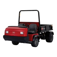
1. Hydraulic reservoir
2. Gear pump
3. Hydraulic manifold
Figure 47
2
1
3
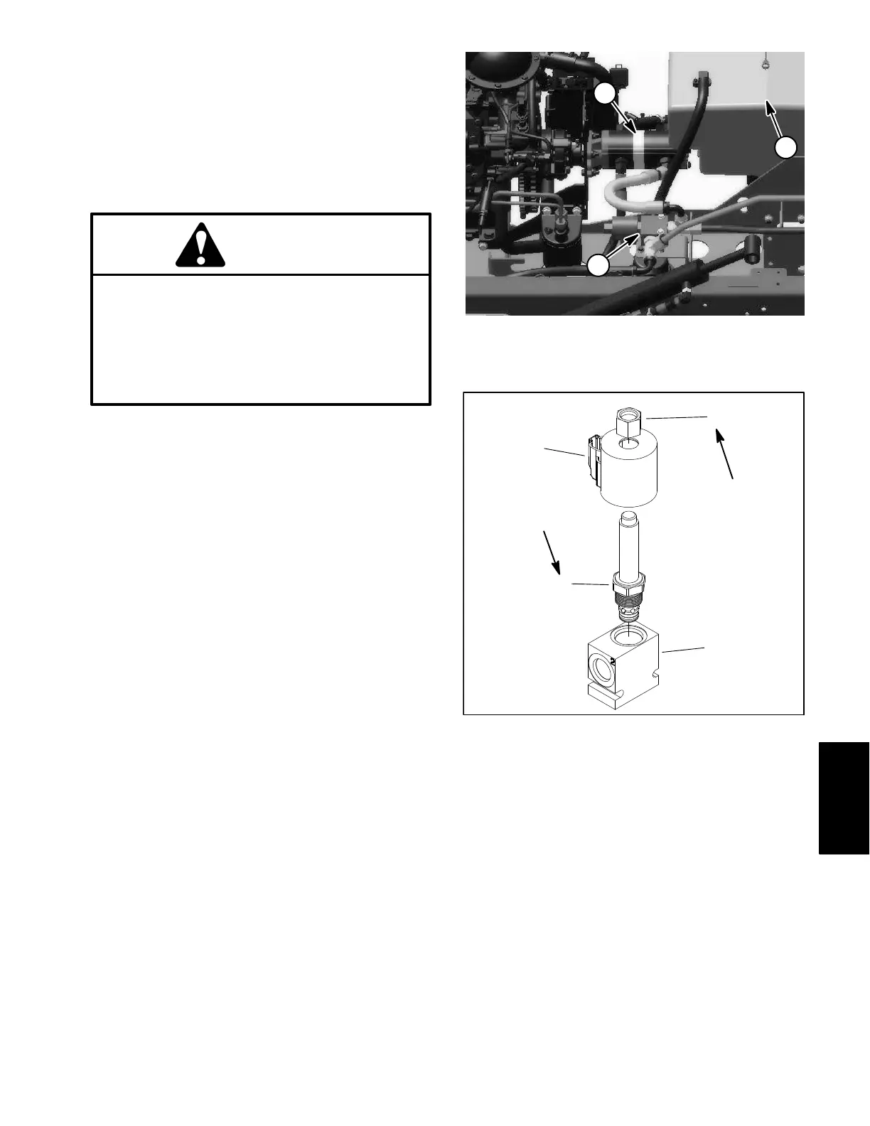
1. Nut
2. Solenoid coil
3. Solenoid cartridge valv
4. Manifold body
Figure 48
1
2
3
4
5 ft−lb
(6.8 N−m)
25 ft−lb
(34 N−m)
5. Visually inspect cartridge valve for damaged sealing
surfaces and contamination.
A. Contamination may cause valves to stick or hang
up. Contamination can become lodged in small valve
orifices or seal areas causing malfunction.
B. If valve sealing surfaces appear pitted or dam-
aged, the hydraulic system may be overheating or
there may be water in the system.
Hydraulic
System