Motors
Fans
Sensors
Switches
Electromagnetic spring clutches
Solenoids
PC boards
Lamps, coils, and heaters
Thermistors, thermopiles, and thermostats
Transformer
Others
Symbol Name Figure
Wire harness
location
MR1
FEED-MOT
Original feed motor
[A]-2 3-F
MR2
READ-MOT
Read motor
[A]-2 3-F
MR3
SB-MOT
Original reverse motor
[A]-2 3-F
MR4
EXIT-MOT
Original exit motor
[A]-2 3-G
M1
SCAN-MOT
Scan motor
[B] 2-F
M2
EXIT-MOT
Exit motor
[C] 6-H
M3
REV-MOT
Reverse motor
[C] 6-H
M4
BRIDGE-ENT-MOT
Bridge unit transport entrance motor
[C] 6-H
M5
BRIDGE-EXIT-MOT
Bridge unit transport exit motor
[C] 6-G
M6
FUS-MOT
Fuser motor
[D]-1 6-D
M7
ADU-MOT-1
ADU motor-1
[J] 8-D
M8
ADU-MOT-2
ADU motor-2
[J] 8-D
M9
TR2-MOT
2nd transfer motor
[G] 4-A
M10
TRU-WASTE-TNR-MOT
TRU waste toner motor
[G] 7-D
M11
TRU-WASTE-TNR-TEPT-MOT
TRU waste toner transport motor
[G] 8-E
M12
SFB-MOT
Bypass motor
[L] 8-D
M13
TBU-MOT
Transfer belt motor
[F] 7-E
M14
TBU-CAM-MOT
Transfer belt cam motor
[F] 7-E
M15
TNR-MOT-K
Toner motor-K
[I] 6-E
M16
TNR-MOT-C
Toner motor-C
[I] 6-D
M17
TNR-MOT-M
Toner motor-M
[I] 6-D
M18
TNR-MOT-Y
Toner motor-Y
[I] 6-D
M19
SUB-HOP-MOT-K
Sub-hopper toner motor-K
[E]-3 8-B
M20
SUB-HOP-MOT-C
Sub-hopper toner motor-C
[E]-3 8-A
M21
SUB-HOP-MOT-M
Sub-hopper toner motor-M
[E
]-3 7-B
M22
SUB-HOP-MOT-Y
Sub-hopper toner motor-Y
[E]-3 7-A
M23
CH-CLN-MOT-K
Needle electrode cleaner motor-K
[E]-3 8-C
M24
CH-CLN-MOT-C
Needle electrode cleaner motor-C
[E]-3 8-B
M25
CH-CLN-MOT-M
Needle electrode cleaner motor-M
[E]-3 7-C
M26
CH-CLN-MOT-Y
Needle electrode cleaner motor-Y
[E]-3 7-B
M27
DRM-MOT-K
Drum motor-K
[E]-1 4-B
M28
DRM-MOT-YMC
Drum motor-YMC
[E]-1 4-B
M29
DEV-MOT-K
Developer unit motor-K
[E]-1 5-F
M30
K-DEV-MIX-MOT
Developer unit mixer motor-K
[E]-1 5-E
M31
DEV-MOT-YMC
Developer unit motor-YMC
[E]-1 4-C
M32
DEV-MIX-MOT-YMC
Developer unit mixer motor-YMC
[E]-1 4-B
M33
WASTE-TNR-TRPT-MOT
Waste toner transport motor
[I] 6-C
M34
POL-MOT
Polygonal motor
[H] 5-D
M35
MIR-MOT-M
Mirror motor-M
[H] 5-C
M36
MIR-MOT-C
Mirror motor-C
[H] 5-D
M37
MIR-MOT-K
Mirror motor-K
[H] 5-D
M38
SHT-MOT
Shutter motor
[H] 5-C
M39
RGST-MOT
Registration motor
[G] 6-H
M40
TRNS-MOT-1
Transport motor-1
[M]-1 6-H
M41
TRNS-MOT-2
Transport motor-2
[M]-1 7-H
M42
FEED-MOT
Feed motor
[M]-1 7-H
M43
FED/TR-MOT
Feed/transport motor
[M]-1 8-C
M44
CST-TRY-MOT-1
Tray-up motor-1
[M]-1 8-F
M45
CST-TRY-MOT-2
Tray-up motor-2
[M]-1 8-G
M46
YLCF-TRY-MOT
Tandem LCF tray-up motor
[N] 8-G
M4
7
TLCF-END-MOT
Tandem LCF end fence motor
[N] 8-F
Symbol Name Figure
Wire harness
location
FR1
DF-FAN-MOT
RADF cooling fan
[A]-2 4-H
F1
FAN-SLG-MOT
SLG board cooling fan
[B] 2-G
F2
FAN-INV-MOT
Scanner unit cooling fan-1
[B] 2-G
F3
FAN-REAR-MOT
Exposure lamp cooling fan-1
[B] 2-F
F5
EXIT-PAPER-FAN-MOT-R
Exit paper cooling fan (front)
[C] 7-G
F6
BRIDGE-FAN-MOT-F
Bridge unit cooling fan (front)
[C] 6-G
F7
BRGE-FAN-MOT-R
Bridge unit cooling fan (rear)
[C] 7-G
F8
IH-FAN-MOT-1
IH board cooling fan-1
[D]-2 6-D
F9
IH-FAN-MOT-2
IH board cooling fan-2
[D]-2 6-D
F11
ADU-FAN-MOT
Reversed paper cooling fan
[J] 7-E
F14
EPU-FAN-MOT
EPU cooling fan
[Q] 6-C
F15
EXIT-PAPER-FAN-MOT-F
Exit paper cooling fan (rear)
[D]-1 7-H
F17
EPU-FAN-MOT-K
Main charger blowing fan-K
[E]-3 8-B
F18
EPU-FAN-MOT-C
Main charger blowing fan-C
[E]-3 8-B
F19
EPU-FAN-MOT-M
Main charger blowing fan-M
[E]-3 7-B
F20
EPU-FAN-MOT-Y
Main charger blowing fan-Y
[E]-3 7-B
F21
TNR-CTRG-FAN-MOT
Toner cartridge heat insulation fan
[D]-1 8-C
F22
LSU-FAN-MOT-F
Laser optical unit cooling fan (Front)
[H] 7-C
F23
LSU-FAN-MOT-R
Laser optical unit cooling fan (Rear)
[H] 7-E
F24
QZN-FAN-MOT
Ozone suctioning fan
[Q] 6-C
F25
DEV-FAN-MOT
Scattered toner suctioning fan
[Q] 6-C
F26
FAN-FRONT-MOT
Exposure lamp cooling fan-2
[B] 2-F
F27
SYS-FAN-MOT
SYS board cooling fan
[O] 1-H
F28
HDD-FAN-MOT
HDD cooling fan
[O] 1-H
F29
UPPER-FAN-MOT-L
Upper exhaust fan (left)
[Q] 8-C
F30
UPPER-FAN-MOT-R
Upper exhaust fan (right)
[Q] 8-C
F31
TNR-EX-FAN-MOT
Toner cooling exhaust fan
[Q] 7-C
F32
UP-EXIT-FAN-MOT-1
Up
per exit section cooling fan-1
[Q] 7-F
F33
UP-EXIT-FAN-MOT-2
Upper exit section cooling fan-2
[Q] 7-F
F34
LOW-EXIT-FAN-MOT-1
Lower exit section cooling fan-1
[Q] 7-F
F35
LOW-EXIT-FAN-MOT-2
Lower exit section cooling fan-2
[Q] 7-F
F36
LOW-EXIT-FAN-MOT-3
Lower exit section cooling fan-3
[Q] 7-F
F37
PS-FAN-MOT-1
Power supply unit cooling fan-1
[P] 4-G
F38
PS-FAN-MOT-2
Power supply unit cooling fan-2
[P] 4-G
Symbol Name Figure
Wire harness
location
SR1
TRAY LENGTH-SNR
Original tray sensor
[A]-1 3-E
SR2
TRAY WIDTH-SNR
Original tray width sensor
[A]-1 3-F
SR3
EMPTY-SNR
Original empty sensor
[A]-1 4-E
SR4
READ OUT-SNR
Original reading end sensor
[A]-1 4-G
SR5
RGT-SNR
Original registration sensor
[A]-1 4-F
SR6
WIDTH1-SNR
Original width detection sensor-1
[A]-1 4-E
SR7
WIDTH2-SNR
Original width detection sensor-2
[A]-1 4-F
SR8
WIDTH3-SNR
Original width detection sensor-3
[A]-1 4-F
SR9
MIDDLE-SNR
Original intermediate transport sensor
[A]-1 4-G
SR10
READ IN-SNR
Original reading start sensor
[A]-1 4-G
SR11
EXITR-SNR
Original exit/reverse sensor
[A]-1 4-F
SR12
EXIT-SNR
Original exit sensor
[A]-1 4-G
SR13
JAM COVER-UPPER-SNR
Original jam access cover opening/closing
sensor
[A]-1 4-E
SR14
JAM COVER-LOWER-SNR
Original reverse unit opening/closing sensor
[A]-1 4-G
SR15
DF OPEN-SNR
RADF opening/closing sensor
[A]-1 4-G
S1
APS-2
Automatic original detection sensor (APS-2)
[B] 2-E
S2
APS-C
Automatic original detection sensor (APS-C)
[B] 2-E
S3
APS-1
Automatic original detection sensor (APS-1)
[B] 2-E
S4
AP
S-3
Automatic original detection sensor (APS-3)
[B] 2-E
S5
APS-R
Automatic original detection sensor (APS-R)
[B] 2-E
S6
HOME-SNR
Carriage home position sensor
[B] 2-F
Symbol Name Figure
Wire harness
location
S7
PLTN-SNR
Platen sensor
[B] 2-E
S8
TNR-SNR-K
Toner cartridge paddle rotation detection sensor-
K
[I] 6-E
S9
TNR-SNR-C
Toner cartridge paddle rotation detection sensor-
C
[I] 6-D
S10
TNR-SNR-M
Toner cartridge paddle rotation detection sensor-
M
[I] 6-D
S11
TNR-SNR-Y
Toner cartridge paddle rotation detection sensor-
Y
[I] 6-D
S12
TEMP/HUMI-SNR
Temperature/humidity sensor
[E]-2 7-C
S13
WASTE-TNR-AMOT-SNR
Waste toner amount detection sensor
[I] 6-C
S14
WASTE-TNRFLL-SNR
Waste toner box full detection sensor
[I] 6-B
S16
WASTE-TNR-BOX-SNR
Waste toner detection sensor
[I] 6-C
S17
TRU-WASTE-TNR-AMT-SNR
TRU waste toner amount detection sensor
[K] 8-E
S20
IMG-POS-SNR-F
Image position aligning sensor (front)
[G] 6-D
S21
IMG-POS-SNR-C
Image position aligning sensor (center)
[G] 6-C
S22
IMG-POS-SNR-R
Image position aligning sensor (rear)
[G] 6-C
S23
TNR-LVL-SNR
Image quality sensor
[G] 6-C
S24
SHT-SNR-HP
Shutter sensor (home position)
[H] 5-C
S25
SHT-SNR-EP
Shutter sensor (end position)
[H] 5-C
S26
ATTNR-SNR-K
Auto-toner sensor-K
[E]-2 8-C
S27
ATTNR-SNR-C
Auto-toner sensor-C
[E]-2 8-B
S28
ATTNR-SNR-M
Auto-toner sensor-M
[E]-2 7-C
S29
ATTNR-SNR-Y
Auto-toner sensor-Y
[E]-2 7-B
S30
CH-CLN-SNR-K
Needle electrode cleaner detection sensor-K
[E]-2 8-C
S31
CH-CLN-SNR-C
Needle electrode cleaner detection sensor-C
[E]-2 8-A
S32
CH-CLN-SNR-M
Needle electrode cleaner detection sensor-M
[E]-2 7-B
S33
CH-CLN-SNR-Y
Needle electrode cleaner detection sensor-Y
[E]-2 7-B
S34
-
Drum surface potential (V0) sensor-K
[E]-2 8-A
S35
-
Dr
um surface potential (V0) sensor-C
[E]-2 8-A
S36
-
Drum surface potential (V0) sensor-M
[E]-2 8-A
S37
-
Drum surface potential (V0) sensor-Y
[E]-2 8-A
S38
SUB-HOP-TNR-SNR-K
Sub-hopper toner sensor-K
[I] 8-B
S39
SUB-HOPTNR-SNR-C
Sub-hopper toner sensor-C
[I] 8-A
S40
SUB-HOPTNR-SNR-M
Sub-hopper toner sensor-M
[I] 8-A
S41
SUB-HOP-TNR-SNR-Y
Sub-hopper toner sensor-Y
[I] 8-B
S42
AUG-LOCK-SNR
Auger lock detection sensor
[I] 7-C
S43
YMC-DRM-PHASE-SNR
Color drum phase sensor
[E]-1 5-E
S44
K-DRM-PHASE-SNR
K drum phase sensor
[E]-1 5-E
S46
TBU-CONT-SNR
Transfer belt contact/release detection sensor
[F] 7-E
S47
CLNG-SNR
Transfer belt paper clinging detection sensor
[G] 6-C
S48
PRPOS-SNR
Fuser unit contact/release detection sensor
[D]-1 6-B
S49
HRLOCK-SNR
Fuser belt rotation detection sensor
[D]-1 6-B
S50
TR2-SNR
2nd transfer roller contact/release detection
sensor
[G] 6-C
S51
TR2-CLNG-SNR
2nd transfer side paper clinging detection sensor
[G] 8-D
S52
RGST-SNR
Registration sensor
[G] 7-G
S55
BRIDGE-ENT-SNR
Bridge unit path entrance sensor
[C] 6-G
S56
BRIDGE-EXIT-SNR
Bridge unit path exit sensor
[C] 6-G
S57
REV-PATH-SNR
Reverse path sensor
[C] 6-G
S58
REV-JAM-SNR
Reverse section stationary jam detection sensor
[C] 6-G
S59
REV-PATH-OPEN-SNR
Reverse sensor
[C] 7-H
S60
REV-JAM-SNR
Reverse section paper transport detection sensor
[C] 7-H
S61
UP-EXIT-SNR
Upper paper exit sensor
[C] 7-G
S62
UP-EXIT-SNR
Upper exit tray paper full detection sensor
[C] 7-G
S63
LOW-EXIT-SNR
Lower paper exit sensor
[C
] 7-G
S64
ADU-OPEN-SNR
Duplexing unit opening/closing detection sensor
[J] 7-G
S65
FUS-TRPT-SNR
Fuser transport sensor
[D]-1 8-D
Symbol Name Figure
Wire harness
location
S66
ADU-ENT-SNR
Duplexing unit path entrance sensor
[J] 8-D
S67
ADU-EXIT-SNR
Duplexing unit path exit sensor
[J] 8-D
S69
MEDIA-SNR
Media sensor
[L] 8-E
S70
SFB-SIZE-SNR
Bypass paper size detection sensor
[L] 8-E
S71
SFB-SNR
Bypass paper sensor
[L] 8-C
S72
SFB-FEED-SNR
Bypass feed sensor
[L] 8-C
S73
CST1-SNR
1st drawer detection sensor
[M]-2 8-D
S74
CST1-BTM-SNR
1st drawer bottom sensor
[M]-1 8-F
S75
CST1-EMP-SNR
1st drawer empty sensor
[M]-2 8-D
S76
CST1-TRY-SNR
1st drawer tray-up sensor
[M]-2 8-D
S77
CST1-TRNS-SNR
1st drawer transport sensor
[M]-2 8-D
S78
CST1-FEED-SNR
1st drawer feed sensor
[M]-2 8-D
S79
CST1-SIZE-SNR-1
1st drawer paper size detection sensor-1
[M]-1 8-F
S80
CST1-SIZE-SNR-2
1st drawer paper size detection sensor-2
[M]-1 8-F
S81
CST2-SNR
2nd drawer detection sensor
[M]-2 8-E
S82
CST2-BTM-SNR
2nd drawer bottom sensor
[M]-1 8-F
S83
CST2-EMP-SNR
2nd drawer empty sensor
[M]-2 8-E
S84
CST2-TRY-SNR
2nd drawer tray-up sensor
[M]-2 8-E
S85
CST2-TRNS-SNR
2nd drawer transport sensor
[M]-2 8-E
S86
CST2-FEED-SNR
2nd drawer feed sensor
[M]-2 8-E
S87
CST2-SIZE-SNR-1
2nd drawer paper size detection sensor-1
[M]-1 8-F
S88
CST2-SIZE-SNR-2
2nd drawer paper size detection sensor-2
[M]-1 8-G
S89
CST3/LCF-SNR
3rd drawer/tandem LCF detection sensor
[M]-2 8-F
S90
CST3-BTM-SNR
3rd drawer bottom sensor
[M]-1 8-G
S91
CST3/LCF-EMP-SNR
3rd drawer/tandem LCF empty sensor
[M]-2 8-F
S92
CST3/LCF-TRY-SNR
3
rd drawer/tandem LCF tray-up sensor
[M]-2 8-E
S93
CST3/LCF-TRNS-SNR
3rd drawer/tandem LCF transport sensor
[M]-2 8-E
S94
CST3/LCF-FEED-SNR
3rd drawer/tandem LCF feed sensor
[M]-2 8-F
S95
CST3-SIZE-SNR-1
3rd drawer paper size detection sensor-1
[M]-1 8-G
S96
CST3-SIZE-SNR-2
3rd drawer paper size detection sensor-2
[M]-1 8-G
S97
CST4-SNR
4th drawer detection sensor
[M]-2 7-F
S98
CST4-BTM-SNR
4th drawer bottom sensor
[M]-1 8-H
S99
CST4-EMP-SNR
4th drawer empty sensor
[M]-2 7-F
S100
CST4-TRY-SNR
4th drawer tray-up sensor
[M]-2 7-E
S101
CST4-TRNS-SNR
4th drawer transport sensor
[M]-2 7-E
S102
CST4-FEED-SNR
4th drawer feed sensor
[M]-2 7-F
S103
CST4-SIZE-SNR-1
4th drawer paper size detection sensor-1
[M]-1 8-H
S104
CST4-SIZE-SNR-2
4th drawer paper size detection sensor-2
[M]-1 8-H
S106
TLCF-STTBY
Standby side tray paper amount detection sensor
[N] 8-G
S107
TLCF-BTM-SNR
Tandem LCF bottom sensor
[N] 8-H
S108
TLCF-STBY-TRY-SNR
Standby side tray detection sensor
[N] 8-F
S109
TLCF-STTBY
Standby side empty sensor
[N] 8-G
S110
TLCF-STPR-SNR-R
Stopper opening/closing detection sensor (front)
[N] 8-H
S111
TLCF-STPR-SNR-F
Stopper opening/closing detection sensor (rear)
[N] 8-H
S112
TLCF-HOME-SNR
End fence home position sensor
[N] 8-G
S113
TLCF-STP-SNR
End fence stop position sensor
[N] 8-G
S114
FEED-COV-SNR
Feed cover sensor
[K] 7-C
Symbol Name Figure
Wire harness
location
SWR1
JAM COVER-SW
Jam access cover opening/closing switch
[A]-1 3-E
SWR2
DF OPEN-SW
RADF opening/closing switch
[A]-1 3-E
SW1 Main power switch [K]
AC
Wire Harness
SW2 Interlock switch [J]
AC
Wire
Harness
SW3
TNR-MOT-SW
Toner motor interlock switch
[K] 6-E
SW4 Duplexing unit interlock switch [J]
AC
Wire Harness
Symbol Name Figure
Wire harness
location
SW5
REV-PATH-COV-SW
Reverse path cover switch
[C] 7-H
SW7
Duplexing unit cover opening/closing detection
switch
[J]
AC
Wire Harness
SW8 Bridge unit connecting detection switch [K]
AC
Wire Harness
SW9
FRONT-COV-SW
Front cover opening/closing detection switch
[K] 6-E
Symbol Name Figure
Wire harness
location
CLT1
PRS-ROL-CLT
Pressure roller contact/release clutch
[D]-1 7-E
CLT2
TR2-CONT-CLT
2nd transfer roller contact/release clutch
[G] 7-F
CLT3
TR2-DRV-CLT
2nd transfer roller drive clutch
[G] 7-F
CLT4
CST3-TR-CLT
3rd drawer transport clutch
[M]-1 8-B
CLT5
CST3-FEED-CLT
3rd drawer feed clutch
[M]-1 8-B
CLT6
CST4-TR-CLT
4th drawer transport clutch
[M]-1 8-B
CLT7
CST4-FEED-CLT
4th drawer feed clutch
[M]-1 8-B
Symbol Name Figure
Wire harness
location
SOLR1
PICKUP-SOL
Original pickup solenoid
[A]-2 2-G
SOLR2
SB-SOL
Original reverse solenoid
[A]-2 2-G
SOLR3
GATE-SOL
Original exit solenoid
[A]-2 2-G
SOL1
TRNS-SOL-1
Transport path switching solenoid-1
[C] 6-F
SOL2
TRNS-SOL-2
Transport path switching solenoid-2
[C] 6-F
SOL3
SNR-SHUT-SOL
Image quality shutter solenoid
[G] 6-C
SOL4
V0-SHUT-SOL-K
V0 sensor shutter solenoid-K
[E]-3 8-C
SOL5
V0-SHUT-SOL-C
V0 sensor shutter solenoid-C
[E]-3 8-B
SOL6
V0-SHUT-SOL-M
V0 sensor shutter solenoid-M
[E]-3 7-C
SOL7
V0-SHUT-SOL-Y
V0 sensor shutter solenoid-Y
[E]-3 7-B
SOL8
SFB-SOL
Bypass pickup solenoid
[L] 8-E
SOL9
TLCF-SOL
Tandem LCF solenoid
[N] 8-F
SOL10
TLCF-STPR-SOL-F
Stopper opening/closing solenoid (front)
[N
] 8-G
SOL11
TLCF-STPR-SOL-R
Stopper opening/closing solenoid (rear)
[N] 8-H
Symbol Name Figure
Wire harness
location
DLG
PWA-D-DLG
RADF control PC board
[A]-2 3-G
CCD
PWA-F-CCD
CCD driving PC board (CCD board)
[B] 2-F
SLG
PWA-F-SLG
Scanning section control PC board (SLG board)
[B] 2-E
INV
INV
Lamp inverter board
[B] 2-F
DSP
PWA-F-DSP
Display PC board (DSP board)
[S] 1-B
KEY1
PWA-F-KEY1
Key PC board-1 (KEY-1 board)
[S] 1-B
KEY2
PWA-F-KEY2
Key PC board-2 (KEY-2 board)
[S] 1-B
P-INV
P-INV
Panel inverter board (P-INV board)
[S] 1-A
IMG
PWA-F-IMG
Image processing PC board (IMG board)
[O] 4-D
SYS
PWA-F-SYS
System control PC board (SYS board)
[O] 2-A
LGC
PWA-F-LGC
Logic PC board (LGC board)
[O] 5-A
SNS
PWA-F-SNS
H-sync detection PC board (SNS board)
[H] 5-E
LDR-Y
PWA-F-LDR-Y
Laser driving PC board-Y (LDR-Y board)
[H] 5-D
LDR-M
PWA-F-LDR-M
Laser driving PC board-M (LDR-M board)
[H] 5-B
LDR-C
PWA-F-LDR-C
Laser driving PC board-C (LDR-C board)
[H] 5-D
LDR-K
PWA-F-LDR-K
Laser driving PC board-K (LDR-K board)
[H] 5-B
EPU
PWA-F-EPU
EPU PC board (EPU board)
[E]-3 7-A
V0S
PWA-F-V0
Drum surface potential sensors control PC board
(V0S board)
[E]-3 8-A
PFC
PWA-F-PFC
Paper feeding control PC board (PFC board)
[O] 7-C
ADU
PWA-F-ADU
ADU control PC board (ADU board)
[J] 8-D
DRV
PWA-F-DRV
DRV PC board
[C] 7-G
IH
PWA-F-IH
Heater control PC board (IH board)
[D]-2 6-D
FIL
PWA-F-FIL
Filter PC board (FIL board)
[O] 4-F
SRAM-
S
PW
A-F-SRAM-S
SRAM board <for SYS board>
[O] 2-A
SRAM-
L
PWA-F-SRAM-L
SRAM board <for LGC board>
[O] 5-A
Symbol Name Figure
Wire harness
location
Symbol Name Figure
Wire harness
location
EXP
LP-EXPO
Exposure lamp
[B] 2-F
ERS-K
LP-ERS-K
Discharge LED-K
[E]-3 6-F
ERS-C
LP-ERS-C
Discharge LED-C
[E]-3 6-E
ERS-M
LP-ERS-M
Discharge LED-M
[E]-3 6-E
ERS-Y
LP-ERS-Y
Discharge LED-Y
[E]-3 6-E
LED
PWA-F-LED
Fuser unit jam releasing LED
[J] 8-H
LAMP Pressure roller heater lamp [D]-2
AC
Wire Harness
IH-COIL IH coil [D]-2
AC
Wire Harness
DH1 Scanner damp heater (Left) [R]
AC
Wire Harness
DH2 Scanner damp heater (Right) [R]
AC
Wire Harness
DH3 Drum damp heater [R]
AC
Wire Harness
Symbol Name Figure
Wire harness
location
THM1
THMS-DRM-K
Drum thermistor-K
[E]-2 8-C
THM2
THMS-DRM-Y
Drum thermistor-Y
[E]-2 7-A
THM3
THMS-PR-C
Pressure roller center thermistor
[D]-1 6-A
THM4
THMS-PR-S
Pressure roller side thermistor
[D]-1 6-A
THM5
THMS-PR-E
Pressure roller edge thermistor
[D]-1 6-A
THM6
THMS-FBLT-E
Fuser belt edge thermistor
[D]-1 6-B
THMP1
THMP-FBLT-C
Fuser belt center thermopile
[D]-1 6-B
THMP2
THMP-FBLT-S
Fuser belt side thermopile
[D]-1 6-B
THMO1 Scanner damp heater thermostat [R]
AC
Wire Harness
THMO2 Pressure roller center thermostat [D]-1
AC
Wire Harness
THMO3 Pressure roller side thermostat [D]-1
AC
Wire Harness
THMO4 Fuser belt center thermostat [D]-1
AC
Wire Harness
THMO5 Fuser belt side thermostat [D]-1
AC
Wire Harness
Symbol Name Figure
Wire harness
location
HVT1
PS-HVT1
High-voltage transformer-1
[P] 6-A
HVT2
PS-HVT1
High-voltage transformer-2
[P
] 6-B
Symbol Name Figure
Wire harness
location
TCP
TCP
Touch panel
[S] 1-A
HDD
HDD
Hard disk
[O] 1-G
PS
PS-ACC
Switching regulator
[P] 5-G
BRK
BRK
Breaker
[P]
AC
Wire Harness
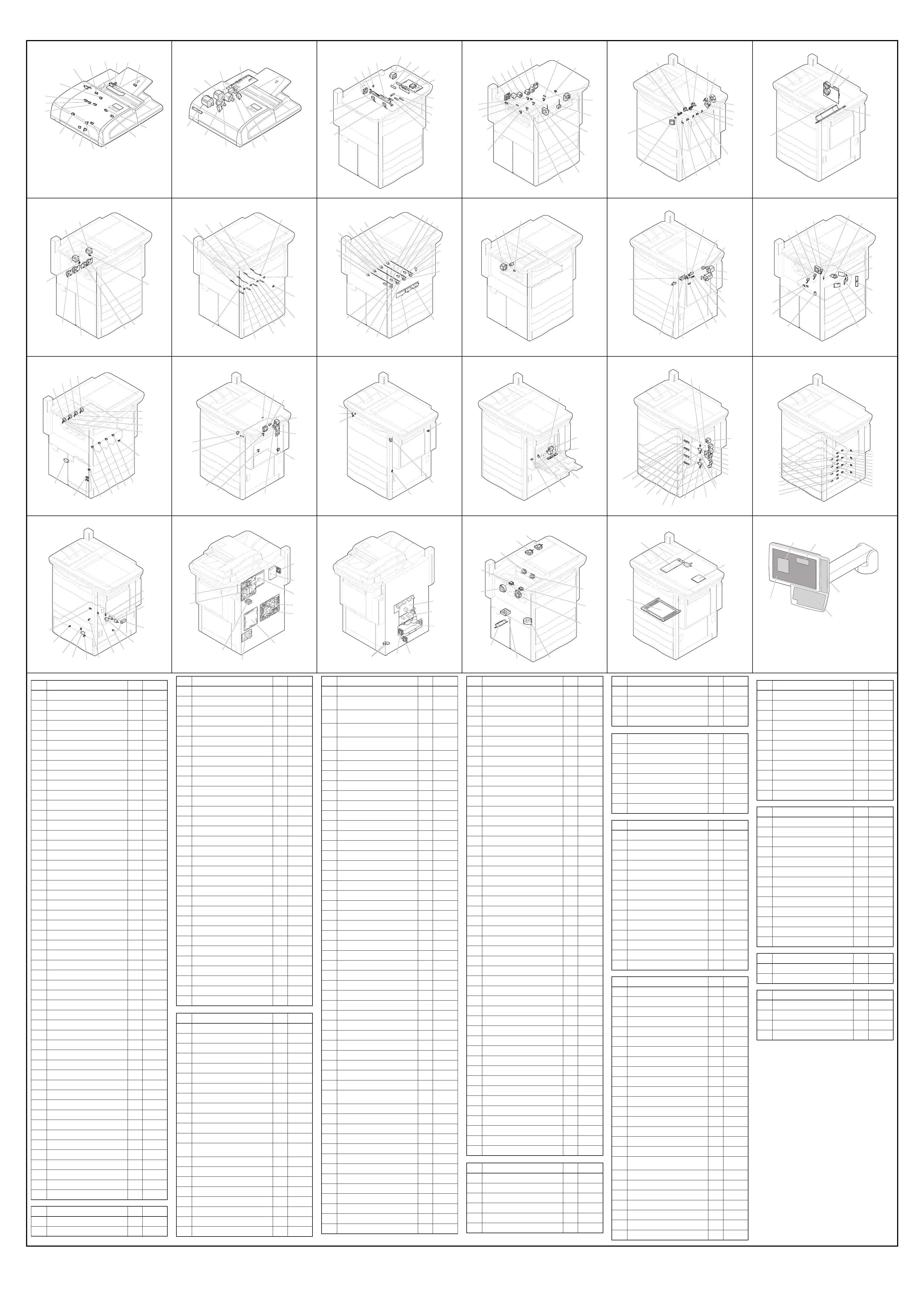
[A]-1 Reversing Automatic Document Feeder (RADF) [A]-2 Reversing Automatic Document Feeder (RADF) [B] Scanner unit [C] Bridge unit/Paper exit [D]-1 Fuser related section [D]-2 Fuser related section
SR1SR2
SWR2
SR3
SR13
SR15
SR5
SR14
SR10
SR9
SR4
SR11
SWR1
SR6
SR7
SR8
SR12
SOLR3
SOLR1
MR3
RADF
SOLR2
FR1
MR4
MR2
MR1
CCD
S4
S3
(A4 series only)
S2
S1
SLG
EXP
F2
F26
F1
S5 (LT series)
S5 (A4 series)
M1
S7
S6
F3
INV
F6
SOL1
F5
S58
S56
SOL2
S61
S62
S63
S60
SW5
S55
S59
S57
M4
M3
M5
M2
DRV
F7
S48
F15
CLT1
M6
S65
THM4
THMP2
THMO4
THMP1
THMO5
THM5
THMO3
THM3
THMO2
S49
F21
THM6
IH
F8
F9
IH-COIL
LAMP
Center heater lamp
Side heater lamp
Sub heater lamp
[E]-1 Developer unit [E]-2 Developer unit [E]-3 Developer unit [F] Transfer belt unit [G] Transfer unit [H] Laser unit
S37
THM2
S36
S35
S34
S29
S33
S32
S31
S12
S30
THM1
S28
S27
S26
M26
ERS-Y
SOL7
SOL6
SOL5
SOL4
M22
M25
M24
ERS-C
ERS-M
M23
ERS-K
F20
F19
F18
F17
M20
M19
M21
V0S
EPU
M39
M9
CLT3
CLT2
SOL3
S22
M10
M11
S21
S52
S50
S51
S47
S20
S23
LDR-K
M34
LDR-M
LDR-C
LDR-Y
SNS
F22
M36
S25
S24
M38
M35
M37
F23
[I] Toner cartridge/Waste toner box [J] Automatic duplexing unit [K] Cover switches/Cover sensor/TRU waste toner box [L] Bypass feed unit [M]-1 Paper feeding section [M]-2 Paper feeding section
S8
S9
S10
S11
S14
S13
M33
S38
S42
S39
S40
S41
S16
M15
M16
M17
M18
M8
ADU
M7
S66
F11
S64
S67
LED
SW2
SW7
SW4
M40
S74
M41
CLT4
CLT5
CLT6
CLT7
M42
M44 M45
S98
S90
S82
S104
S103
S96
S95
S88 S87
S80 S79
M43
S97
S99
S100
S78
S77
S86
S85
S94
S93
S102
S101
S73
S75
S76
S81
S83
S84
S89
S91
S92
10.2 Electric Parts Layout
[N] Tandem LCF [O] PC boards [P] Power supply [Q] Fans [R] Damp heater [S] Control panel
S108
S107
SOL11
SOL9
M47
M46
S111
S109
S106
SOL10
S113
S110
S112
F28
F27
SYS
RAM-S
IMG
PFC
HDD
LGC
RAM-L
FIL
F24
F14
F25
F31
F34
F32
F29
F30
F33
F35
F36
10-2
 Loading...