INSTALLATION
Vertical Express Product Manual 1-7 88600 v.1.0
Installation Section Temporary Operation
Runbug Set Up
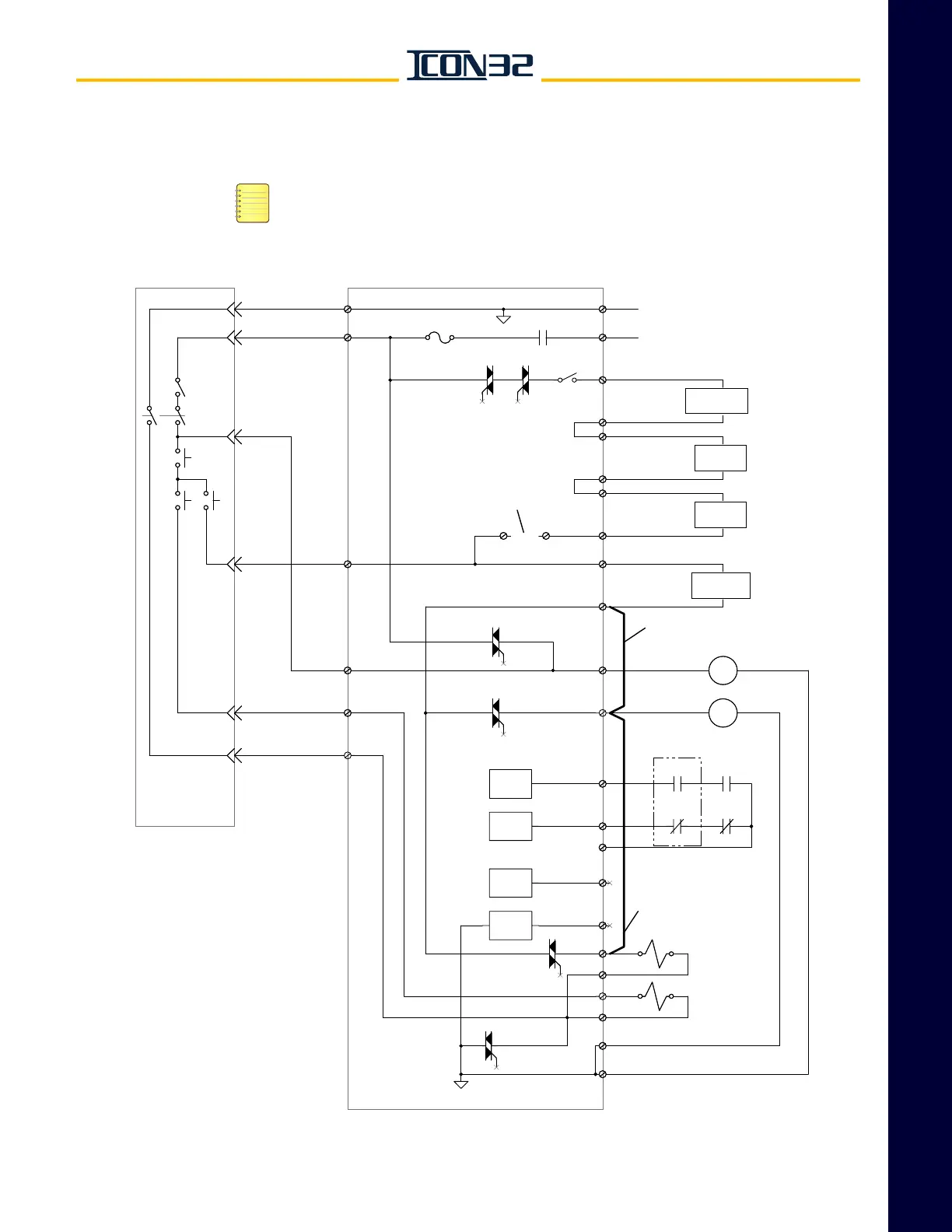
(continued) • For Across The Line Starters - Confirm that there are Manufacturing installed
temporary run jumpers between 134, MCC1 and USS1. See Figure 6.
• The EPEN relay is energized by input EPD2 from the Trades Access Panel.
• On runbug, the CPU Card operation/faults is irrelevant to Up and Down oper-
ation because the operation is dependent on 120VAC discrete feed to relays
and solenoids from the pendant station.
Figure 6 - Temporary Operation Pendant Station (RUNBUG) Connection for Across the Line Motor Starting
AC2
AC2
RUN/STOP
ON/OFF
KEYSWITCH
ENABLE
FROM XFMR1 OR UPS
FROM XFMR1 OR UPS
TSRCPU
TR4
MC1AUX
13 14
MC2AUX
21 22
131
UP SLOW
EPEN
AC2
SAFSP SAFCPU
RUN/STOP
AC2
18:2
121
121
9A:1
MCE
INPUT x1
CPU
TR3
131
9:5
RT
AC1SC
9:3
AC2
9:4
MC2
MC1
TR1
SCG2
MCE
MCF
MCC2
DSS1
G24
MCC1
MCD
MCC2
DOWN SLOW
X1
18:3
TR5
MC2AUX
13 14
9:2
TR6
9:1
9:6
TR2
DSS1
USS2
MUTS
USS1
AC2
USS1
DSS2
131
9A:2
102
MC1AUX
21 22
F-AC1SC
MCC1
107
115
115
107
MCC2
134
MCD
INPUT x1
CPU
MCF
INPUT x1
CPU
MUTS
INPUT x1
CPU
(on Across the Line with
2 Contactors only).
(WHT/BLK)
(RED/BLK)
(WHT)
(BLU)
(ORG)
(BLK)
NO JUMPER
ON RUNBUG
DOWN
UP
REMOTE
INSPECTION
(RUNBUG)
Note: COLOR CODING shown is for
9817323 run button units; other brands
must be wired according to CON TR
pin assignments.
ADD WHEN
ON RUNBUG
ADD WHEN
ON RUNBUG
IOF
MOTOR
PROTECTION
MACHINE-ROOM
EPD's
HOISTWAY
EPD's
CAR
EPD's
BYPASSED
BYPASSED
BYPASSED