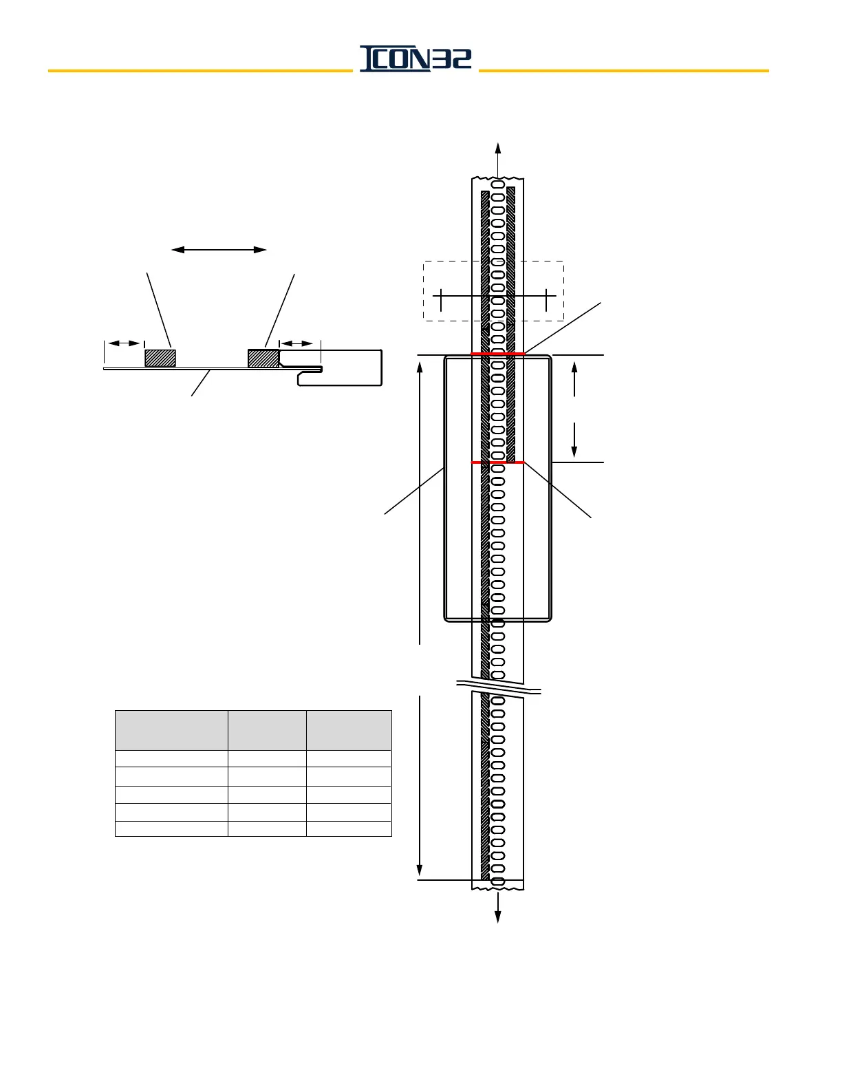
Mark the tape at the
top of selector box.
To top of hoistway
and top tape mount
Contract Speed
(fpm)
0 - 75
76-100
101-125
126-150
151-200
Dimension
T
(inches)
17½
25½
30½
35½
43½
# of Magnets
End to End
4
5
5
6
7
6¼"
Start placement of bottom of terminal
slowdown magnets
T inches below the
tape mark at the top of selector box.
Start placement of directional
limit magnets 6¼" below
the tape mark at the top
of the selector box.
Section A-A
note the difference
No Stripe
(North Pole)
Yellow Stripe
(South Pole)
Slowdown
Magnet(s)
Directional
Limit Magnet(s)
Car Side of Selector Tape
AA
T
Note: The magnets on this sheet
are placed on the back side of the
tape, the side opposite the car side.
½"
½"
To bottom tape mount