Mark the tape at the
top of the selector box.
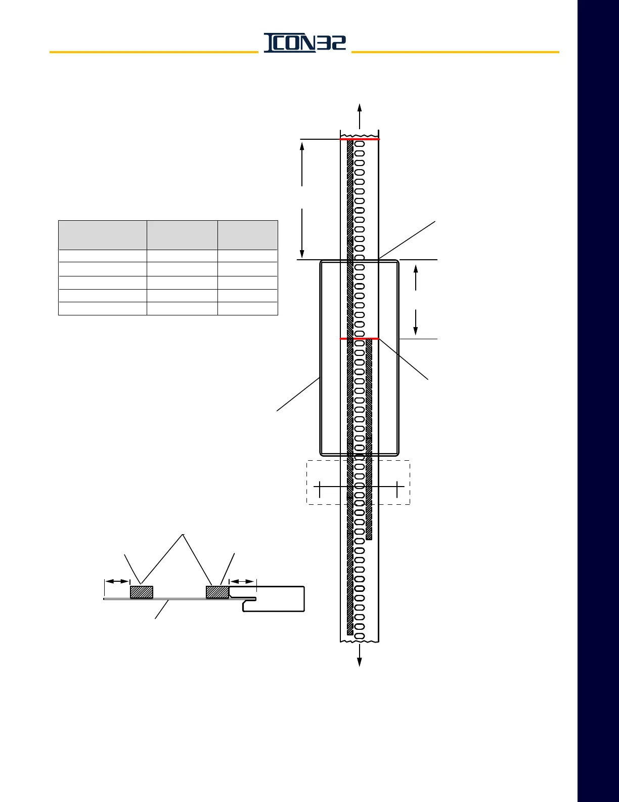
To top of hoistway
and top tape mount
To bottom tape mount
and broken tape switch
Contract Speed
(fpm)
0 - 75
76-100
101-125
126-150
151-200
Dimension
D
(inches)
5
10
15
23
# of Magnets
End to End
3
4
5
5
6
9¼"
Start placement of top of terminal
slowdown magnets
D
inches above the
tape mark at the top of selector box.
Start placement of directional
limit magnets 9¼" below the
tape mark at the top
of the selector box.
BB
Note: The magnets on this sheet
are placed on the back side of the
tape, the side opposite the car side.
D
start 1" below mark
Section B-B
Slowdown
Magnet(s)
½"
Directional
Limit Magnet(s)
Car Side of Selector Tape
Yellow Stripe
(South Pole)
½"
Use alignment tool (850PE1) for
side-to-side alignment of rear magnets
Selector Box